Chapter 3
Connecting the UMI-7774/7772 to Drives and Other Devices
©
National Instruments Corporation
3-23
National Instruments UMI-7774/7772 User Manual
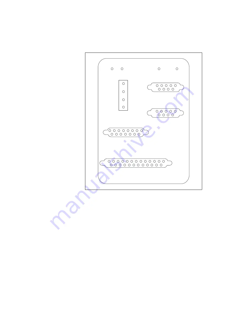
Figure 3-17.
UMI-7774/7772 Pin Locations for Global Stop, Analog Input,
Trigger/Breakpoint, and Digital I/O Connectors
Global Stop
The UMI-7774/7772 has a single 9-pin D-SUB connector for global stop
wiring. This connector includes the Inhibit All input and the Shutdown
input signals. Both signals are optically isolated sinking inputs.
Inhibit All
The Inhibit All signal acts as a global inhibit, and when asserted, activates
the Enable outputs for all of the axes on the UMI-7774/7772.
5
4
3
2
1
9
8
7
6
5
4
3
2
1
9
8
7
6
8
7
6
5
4
3
2
1
15 14 13 12 11 10
9
8
7
6
5
4
3
2
1
9
10
11
12
13
21
20 19
18 17 16 15 14
22
23
24
25
POWER
GLOBAL STOP
V
Viso
INHIBIT ALL
INTERLOCK
V
(24 VDC ±10%)
C
Viso
(5 - 30 VDC)
Ciso
POWER
30 VDC MAX
GLOBAL STOP
ANALOG INPUT
TRIGGER/BREAKPOINT
DIGITAL I/O


