Chapter 3
Connecting the UMI-7774/7772 to Drives and Other Devices
©
National Instruments Corporation
3-7
National Instruments UMI-7774/7772 User Manual
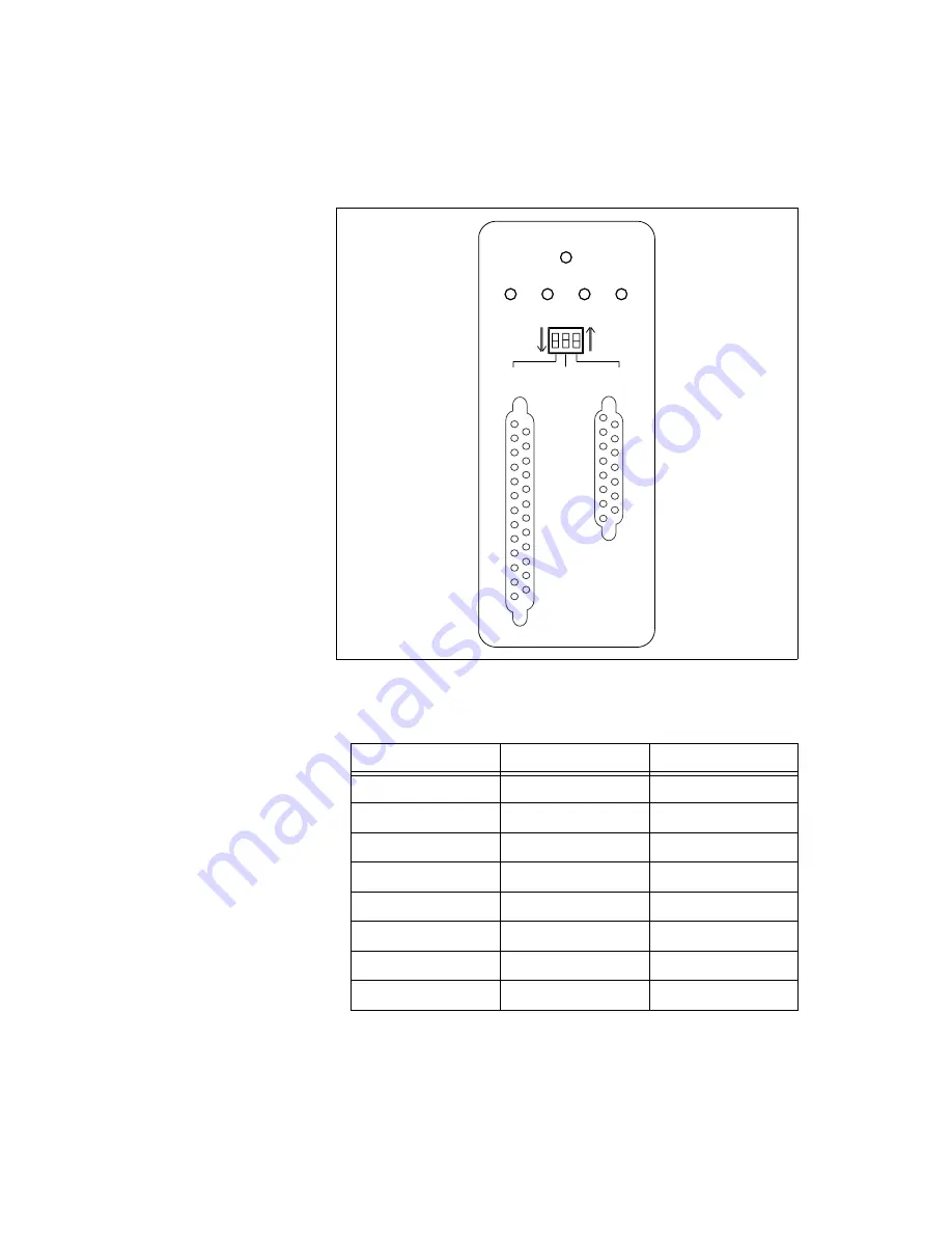
Figure 3-5.
UMI-7774/7772 Per Axis Control and Feedback Connectors, LED Status
Indicators, and Polarity Switches (Axis 1 Shown as Example)
Table 3-2.
Per Axis Control Connector Pin Assignment
Pin
Signal
Optically Isolated
1
Analog Output
No
2
NC
No
3
+5 V (Output)
No
4
Step (CW)
No
5
NC
No
6
Enable
Yes
7
Fault +
Yes
8
Iso Power (Output)
Yes
18
19
20
21
22
23
24
25
17
16
15
14
1
6
7
8
9
10
11
12
13
5
4
3
2
AXIS 1
DISABLED
FAULT
FWD
HOME
REV
ACTIVE
LOW
ACTIVE
HIGH
LIMIT LED
FAULT
ENABLE
CONTROL
FEEDBACK
1
2
3
4
5
6
7
8
9
10
11
12
13
14
15


