Table of Contents
© National Instruments Corporation
ix
VXI-1200 User Manual
Figure 1-1. VXI-1200 Portable Streamlined (5U Wide) Mainframe in
Bench-Top Configuration ................................................................1-3
Figure 1-2. Three Slot Locations for B-Size VXI/VME Modules .........................1-4
Figure 1-3. VXI-1200 Rack-Mount (5U Tall) Configuration ................................1-5
Figure 1-4. Modular Service Friendly Mainframe Design Features ......................1-6
Figure 1-5. VXI-1200 720 Watt Power Supply......................................................1-7
Figure 1-6. VXI-1200 Bench-Top Configuration Positive-Pressure
Cooling System................................................................................1-8
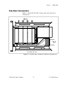
Figure 1-7. VXI-1200 Rack-Mount Configuration Positive-Pressure
Cooling System................................................................................1-9
Figure 2-1. Select VXIbus Slot 0 Controller Location...........................................2-3
Figure 2-2. Airflow Directors.................................................................................2-4
Figure 2-3. Filler Panels .........................................................................................2-6
Figure 2-4. Installing Rack-Mount Door................................................................2-7
Figure 2-5. Connecting Safety Ground ..................................................................2-8
Figure 2-6. Fan Speed Range Selection .................................................................2-9
Figure 3-1. VXI-1200 Front View..........................................................................3-1
Figure 3-2. VXI-1200 Rear View ..........................................................................3-2
Figure 3-3. Powering on the Mainframe ................................................................3-3
Figure 3-4. Using Remote Power On/Standby Switching......................................3-4
Figure 5-1. Cleaning the Fan Filters.......................................................................5-4
Figure 5-2. Removing and Replacing the AC Mains Fuse ....................................5-5
Figure A-1. Mainframe Worst-Case Slot Cooling Curve........................................A-5


