© National Instruments Corporation
4-1
VXI-1200 User Manual
Understanding the
VXI-1200
4
Chapter
This chapter describes the major functional blocks of the VXI-1200
FlexFrame—the power supply, backplane, and cooling system.
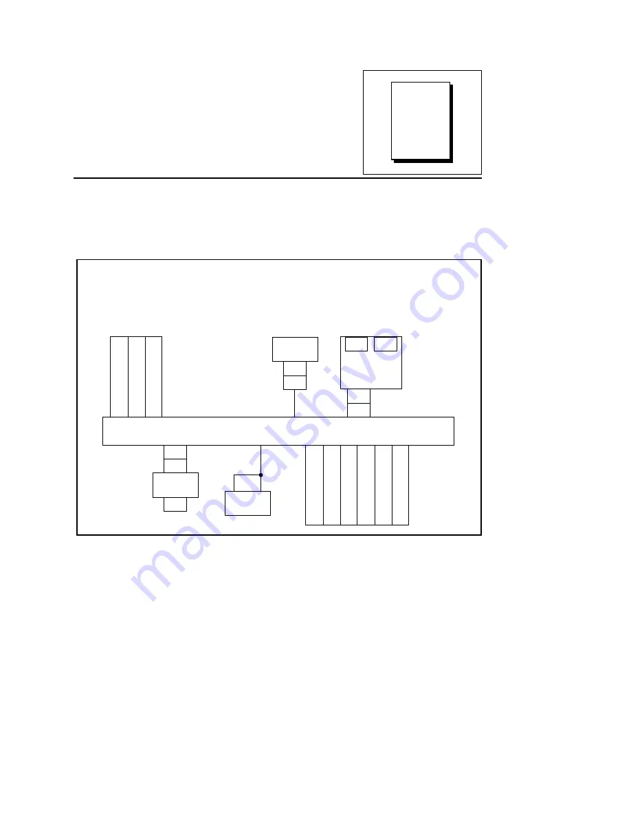
Figure 4-1 shows the functional block diagram of the VXI-1200.
Backplane
Slot B2
Slot B1
Slot B0
Monitor/
Control
F
an Full/3-Quar
ter
Speed Switch
A
C
In
Slot C3
Slot C4
Slot C5
Slot C0
Slot C1
Slot C2
J53
J54
J55
P53
J52
P52
J53
C0
B0
Personality
Module
P355
J355
Fan S1
Assembly
S100
Power
Switch
1
1A
J415
J400
Power Supply
Figure 4-1. VXI-1200 Block Diagram


