Chapter 1
Using the Mainframe
1-4
www.ni.com
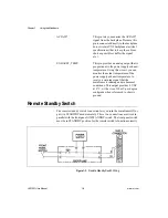
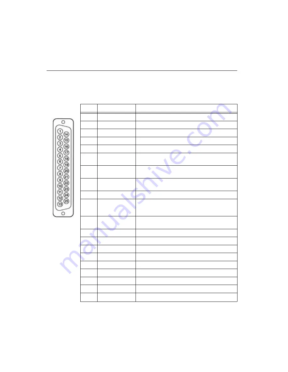
Rear Panel Auxiliary Connector
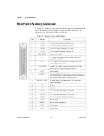
A 25-pin “D” connector is provided on the rear panel of the mainframe to
allow monitoring of power supply voltages and other functions. The
pinouts for this connector are shown in Table 1-1.
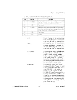
Table 1-1. Connector Pinouts and Description
Pin #
Function
Description
1
+5 VM
+5 V for voltage monitoring (2.4 mA max)
2
–12 VM
–12 V for voltage monitoring (2.4 mA max)
3
–24 VM
–24 V for voltage monitoring (2.4 mA max)
4
–2 VM
–2 V for voltage monitoring (2.4 mA max)
5
REM STDBY
Remote power switch
6
+5 V
+5 V output for charging batteries, running external TTL
circuits, etc. 1 A max
7
+12 V
+12 V output for charging batteries, running external TTL
circuits, relays, etc. 1 A max
8
+5 V STDBY
Input for +5 V standby current (for example, from external
battery). Max 1 A combined total (pins 8 and 21).
9
GND
Chassis ground
10
SYSRESET*
Backplane SYSRESET* signal (input or output). If you use this
pin, be careful not to violate backplane electrical specifications
(that is, keep extender cable as short as possible).
11
EXHAUST_TEMP
An analog output signal proportional to the power supply
exhaust temperature.
12
N/C
Not used
13
N/C
Not used
14
+12 VM
+12 V for voltage monitoring (2.4 mA max)
15
+24 VM
+24 V for voltage monitoring (2.4 mA max)
16
–5.2 VM
–5.2 V for voltage monitoring (2.4 mA max)
17
GND
Chassis ground
18
REM SW
Remote power switch return
19
GND
Chassis ground
20
GND
Chassis ground


