Chapter 1
Using the Mainframe
© National Instruments Corporation
1-5
+5 V
The +5 V output lets you power external
TTL circuitry if required. The maximum
current allowed from this supply is 1.0 A.
+12 V
The +12 V output lets you power a battery
charging circuit to provide a source for
the +5 V STDBY input. The maximum
current allowed from this supply is 1.0 A.
+5 V STDBY
This provides an input to the mainframe
backplane for a +5 V standby power
source. This may be from a separate
battery or power supply. The maximum
current input allowed is 1.0 A. This
means that all standby circuitry in all
modules mounted in the mainframe can
draw a total of 1. 0 A when active.
SYSRESET*
This pin provides an extension of the
backplane SYSRESET* signal. It can be
used to monitor for SYSRESET* or to
send SYSRESET* to the backplane.
Shorting this line to ground inputs a
SYSRESET* signal to the system. If you
use any extension cable out of the 25-pin
D connector on the mainframe rear panel,
make certain that you do not violate VXI
backplane electrical specifications (that
is, keep the cable as short as possible or
buffer the signal, etc.).
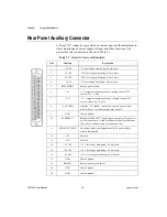
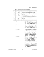
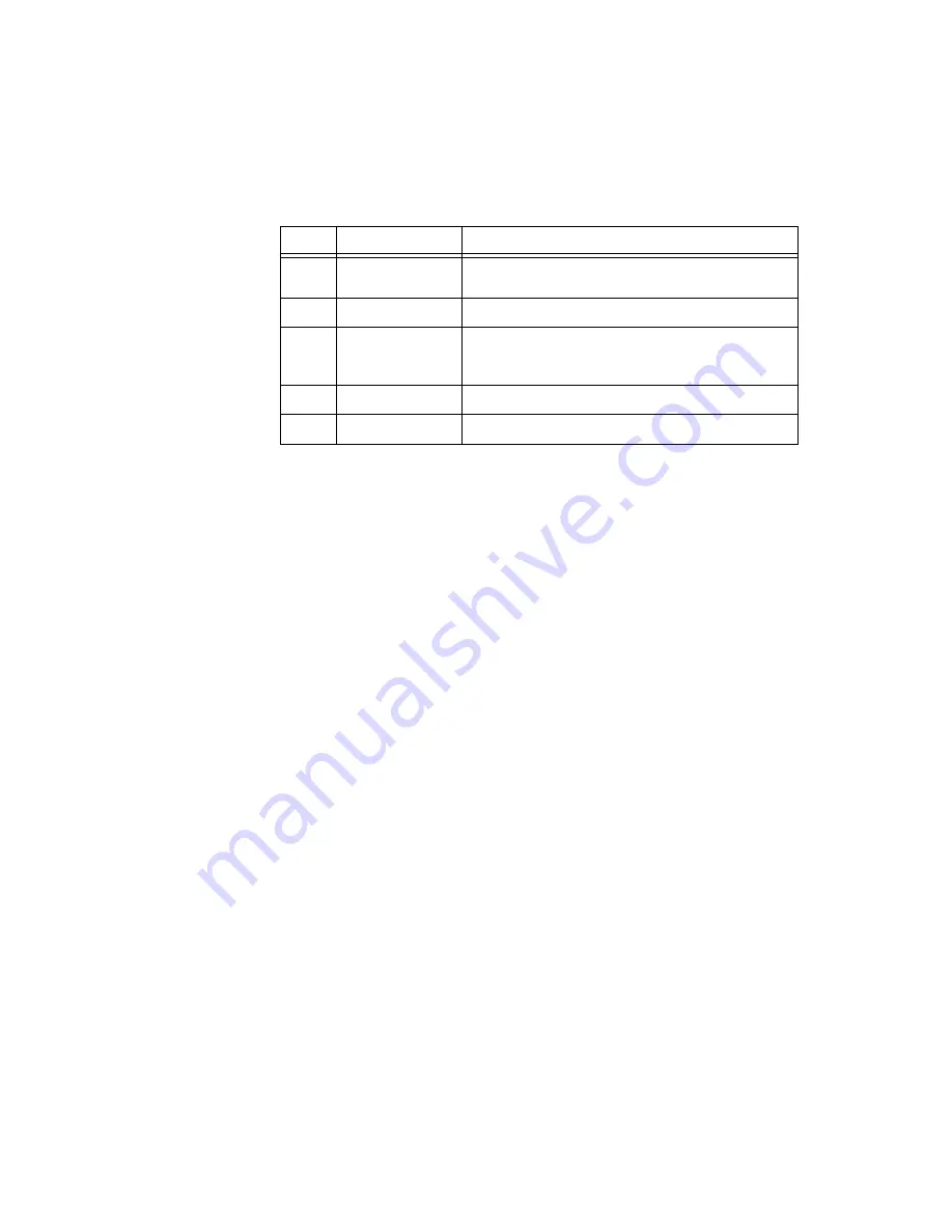
21
+5 V STDBY
Input for +5 V standby current (for example, from external
batter). Max 1 A combined total (pins 8 and 21).
22
GND
Chassis ground
23
AC FAIL*
Backplane AC FAIL* signal (input or output). If you use this pin,
be careful not to violate backplane electrical specifications (that
is, keep extender cable as short as possible).
24
GND
Chassis ground
25
N/C
Not used
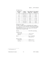
Table 1-1. Connector Pinouts and Description (Continued)
Pin #
Function
Description