


Appendix D
Front Panel and Connectors
VXIpc-850 Series User Manual
D- 4
© National Instruments Corporation
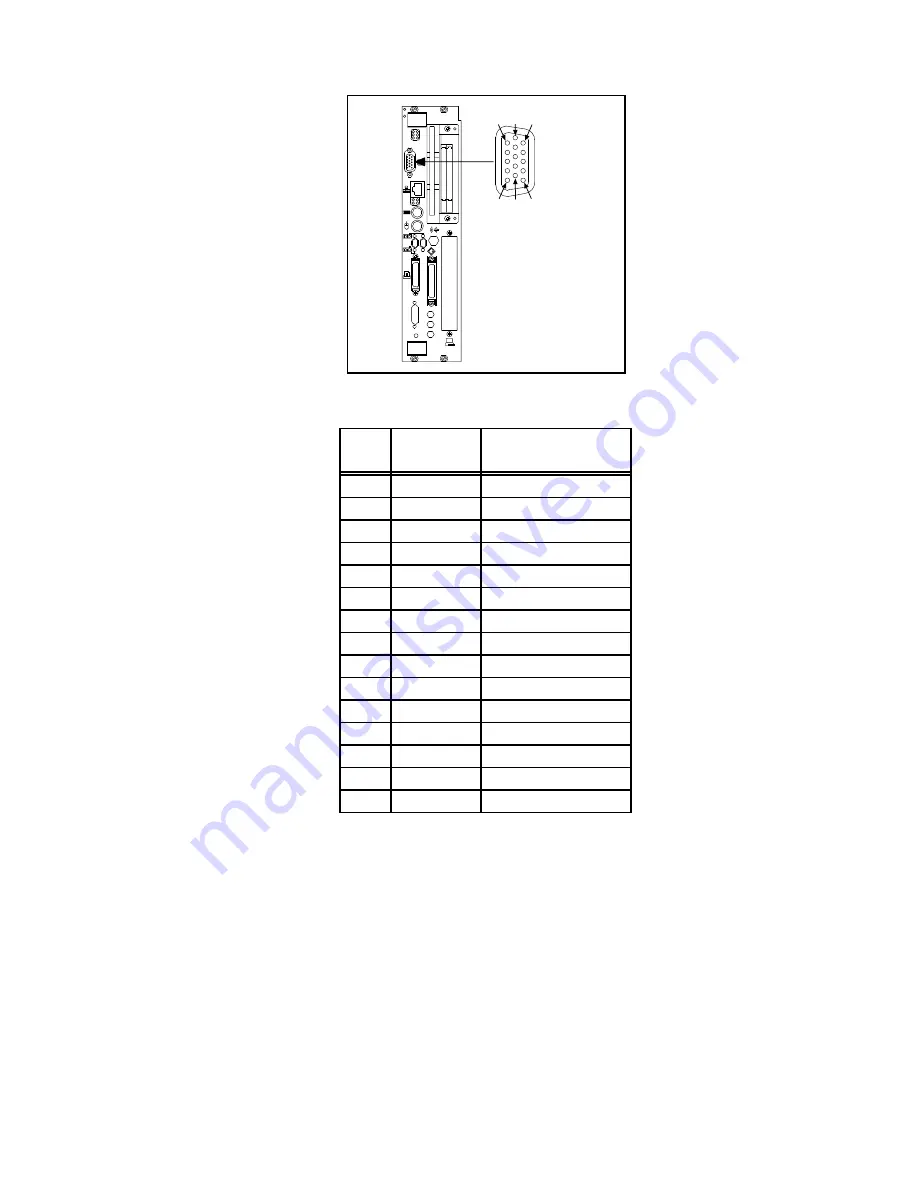
VGA
1
6
11
5
10
15
2
1
Figure D-3. VGA Connector Location and Pinout
Table D-2. VGA Connector Signals
Pin
Signal
Name
Signal Description
1
R
Red
2
G
Green
3
B
Blue
4
NC
Not Connected
5
GND
Ground
6
GND
Ground
7
GND
Ground
8
GND
Ground
9
+5 VDC
+5 Volts
10
GND
Ground
11
NC
Not Connected
12
SD
Serial Data
13
HSync
Horizontal Sync
14
VSync
Vertical Sync
15
SC
Serial Clock


