Chapter 3
Configuration and Default Settings
©
National Instruments Corporation
3-7
VXIbus CLK10 Routing and Termination
When the VXIpc 870 Series is installed in Slot 0 of your mainframe, it
supplies the VXIbus CLK10 signal. The VXIpc 870 Series can use two
different sources to generate this signal—an onboard oscillator or the
external CLK SMB connector. The VXIpc 870 Series can also be
configured to drive the external CLK10 SMB from the VXIbus CLK10
signal when in Non-Slot 0.
The VXIpc 870 Series has onboard logic that helps configure the VXIbus
CLK10 routing and termination. You can route the CLK10 signal from
the front panel to the backplane or from the backplane to the front panel.
You also have the option to add a 50
Ω
termination to the signal.
All settings for CLK10 routing and termination are handled through
software. Use T&M Explorer to configure these settings.
Trigger Input Termination
You have the option to terminate the external trigger input SMB with 50
Ω
to ground to match the driving source, if necessary. Use T&M Explorer to
set this option.
MITE EEPROM
The VXIpc 870 Series has an onboard EEPROM, which stores default
register values for the VXI circuitry. These values are loaded when you
power up the computer. These values read from the EEPROM program the
PCI interface and the VXIbus registers so that the VXI interface is ready
to respond to Resource Manager accesses within the required 5 s of
SYSRST* deasserting.
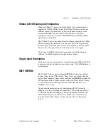
You can disable this power-on self-configuration (POSC) circuit by
changing switch S2. Although this makes the VXI circuitry unusable, it
is sometimes helpful in debugging address and interrupt conflicts with
add-in boards. In general, however, you should leave switch S2 in its
factory-default setting. Figure 3-3 shows the possible configurations
for S2.


