background image

Appendix E

Common Questions

©

National Instruments Corporation

E-3

VXIpc 870 Series User Manual

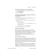
My CMOS is corrupted. How do I set it back to default?

1.

Enter the BIOS setup program as described in Chapter 6,

BIOS

.

2.

Select

Optimal Defaults

.

3.

Select

Save and Exit

.

My operating system is damaged but my hard drive is OK. How can
I re-install the operating system?

Do the following:

1.

Make a bootable floppy disk. Make sure the disk contains

deltree

.

2.

Boot the machine from the disk.

3.

Run

deltree C:\*.*

and answer yes to all files and directories

except

C:\Images

.

If using Windows NT:

Go to

C:\Images\os\wint\I386

directory and run

Winnt /B

.

If using Windows 98:

Go to

C:\Images\os\Win98

and run

Setup

.

4.

Install all IO drivers from

C:\Images\VXI870\...

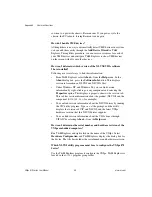
What about running Resman?

Resman is the name of the utility that performs the duties of a VXI
Resource Manager as discussed in the VXIbus specification. When you
set a National Instruments controller to Logical Address 0, you will at some
point need to run Resman to configure your VXI instruments. If your
controller uses a different (non-zero) logical address and is a
message-based device, start Resman before running it on the Logical
Address 0 computer.

When do you need to run Resman?

Run Resman whenever you need to configure your VXI instruments. For
example, if you power-cycle your VXI/VME chassis, your instruments will
be reset, and you will need to run Resman to configure them. You can get
into trouble if you run Resman when your devices are not in a reset state.
Therefore, if you have to run Resman after running it once, you should reset
all of your VXI instruments.

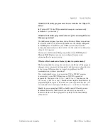
You can perform resource manager operations from within T&M Explorer.
Additionally, you can tell T&M Explorer to run Resman when the
computer first boots up. In this case you may never need to run Resman
explicitly again. You can configure the computer to run Resman at startup,

Summary of Contents for VXIpc 870 Series

Page 1: ...rutilized and idle equipment along with credit for buybacks and trade ins Custom engineering so your equipment works exactly as you specify Critical and expedited services Leasing Rentals Demos In sto...

Page 2: ...VXI VXIpc 870 Series User Manual VXIpc 870 Series User Manual July 2000 Edition Part Number 322116B 01...

Page 3: ...many 089 741 31 30 Greece 30 1 42 96 427 Hong Kong 2645 3186 India 91805275406 Israel 03 6120092 Italy 02 413091 Japan 03 5472 2970 Korea 02 596 7456 Mexico D F 5 280 7625 Mexico Monterrey 8 357 7695...

Page 4: ...or service failures caused by owner s failure to follow the National Instruments installation operation or maintenance instructions owner s modification of the product owner s abuse misuse or neglige...

Page 5: ...ommunications DOC Changes or modifications not expressly approved by National Instruments could void the user s authority to operate the equipment under the FCC Rules Class A Federal Communications Co...

Page 6: ...Directives Readers in the EU EEC EEA must refer to the Manufacturer s Declaration of Conformity DoC for information pertaining to the CE Mark compliance scheme The Manufacturer includes a DoC for most...

Page 7: ...g the VXIpc 870 Series 2 1 Installing and Removing Flash Memory in the VXIpc 873 2 3 Installing the Flash Storage Card 2 3 Removing the Flash Storage Card 2 3 Chapter 3 Configuration and Default Setti...

Page 8: ...4 5 Debugging 4 6 Chapter 5 Functional Overview VXIpc 870 Series Functional Description 5 1 Processor 5 2 Chip Set and SDRAM 5 2 AGP Graphics 5 3 10 100 Ethernet and SCSI 3 5 3 PC CARD Expansion 5 3 P...

Page 9: ...and Installing I O Expansion Boards Appendix E Common Questions Appendix F Technical Support Resources Glossary Index Figures Figure 1 1 VXIpc 871 Embedded Controller 1 1 Figure 1 2 VXIpc 872 Embedde...

Page 10: ...on 1 with Internal Nonremovable Flash Drive C 4 Figure C 4 VXIpc 873 Front Panel Layout and Dimensions Option 2 with Removable Flash Drive C 5 Figure C 5 Keyboard and Mouse Connectors Location and Pin...

Page 11: ...er MXI 2 Bus Tab Default Settings 3 5 Table 4 1 NI VXI VISA Examples 4 4 Table B 1 LEDs and System Startup Status B 2 Table C 1 Keyboard and Mouse Connector Signals C 6 Table C 2 SVGA Connector Signal...

Page 12: ...tions Bold text also denotes parameter names italic Italic text denotes variables emphasis a cross reference or an introduction to a key concept This font also denotes text that is a placeholder for a...

Page 13: ...merMan pdf respectively Use the Acrobat Reader program Version 3 or later to open these files You can also access the NI VXI online help for Windows in the NIVXI folder Refer to the NI VISA User Manua...

Page 14: ...ionally equivalent in many ways These three models differ in that the VXIpc 871 has an internal CD ROM drive while the VXIpc 872 has one AT PCI expansion slot The VXIpc 873 has either an internal nonr...

Page 15: ...Chapter 1 Introduction VXIpc 870 Series User Manual 1 2 www ni com Figure 1 2 VXIpc 872 Embedded Controller Figure 1 3 VXIpc 873 Embedded Controller Option 1 with an Internal Nonremovable Flash Drive...

Page 16: ...lities and C function calls In addition the VXIpc 870 Series has Ethernet capability plus an IEEE 488 2 interface that is compatible with the NI 488 2 architecture The VXIpc 870 Series is a custom com...

Page 17: ...ational Instruments implementation of the VISA specification VISA is a uniform API for communicating and controlling Serial GPIB VXI and VME instruments This API aids in the creation of more portable...

Page 18: ...ure extensive libraries of GPIB Serial and VXI instrument drivers written to take full advantage of direct VXI control LabVIEW and LabWindows CVI include all the tools needed for instrument control da...

Page 19: ...arted VXIpc 870 Series embedded controller VXIbus mainframe Keyboard Mouse Monitor with VGA or better resolution National Instruments software media for the VXIpc 870 Series The NI VXI VISA software i...

Page 20: ...ting on the backplane receptacle connectors Using slow evenly distributed pressure press the module straight in until it seats in the expansion slot The front panel of the VXIpc 870 Series should be e...

Page 21: ...inframe while installing or removing the flash memory Failure to turn off the mainframe will damage the VXIpc 873 the storage card or both 2 Remove the two screws and cover panel on the VXIpc 873 as s...

Page 22: ...r button at the bottom of the flash drive carrier slot until the flash storage card pops out of the drive 4 Slide the card out of the drive Reinstall the cover plate and screws Figure 2 1 Installing a...

Page 23: ...s and switches on the VXIpc 870 Series The diagram also shows the location of the serial and assembly numbers Figure 3 1 VXIpc 870 Series Parts Locator Diagram 1 Ethernet Address 2 CPU Bus Factor W1 W...

Page 24: ...T M Explorer Because you can also use T M Explorer Table 3 1 VXIpc 870 Series Hardware Default Settings Jumper Default Setting Optional Setting J12 Enable automatic Slot 0 detection Force Slot 0 Force...

Page 25: ...vice Tab Default Settings Editor Field Default Setting Logical address 0 Device class Message based Size of Servant area 0 Number of handlers 1 Number of interrupters 0 Table 3 3 VXIpc T M Explorer Sh...

Page 26: ...d Interlocked mode Disabled Assumes no DRAM is installed If DRAM is installed the Address space should be A32 and Requested memory should match the amount of DRAM If you install the DRAM yourself you...

Page 27: ...p and bottom cover to improve EMC performance and to provide easy handling You need to remove the top cover to change many of the switch and jumper settings You must also remove the top cover to chang...

Page 28: ...g it to either Non System Controller or automatic detection configuration Neglecting to do this could result in damage to the device the VXIbus backplane or both Figure 3 2 System Controller Slot Conf...

Page 29: ...outing and termination are handled through software Use T M Explorer to configure these settings Trigger Input Termination You have the option to terminate the external trigger input SMB with 50 to gr...

Page 30: ...ing again Use the procedure as described in the following section How to Fix an Invalid EEPROM Configuration Figure 3 4 shows the configuration settings for EEPROM operation Figure 3 4 EEPROM Configur...

Page 31: ...gs on the VXIpc 870 Series 2 Change switch S1 to the position shown in Figure 3 4b to restore the factory configuration 3 Turn on the computer The computer should boot this time because the factory de...

Page 32: ...jumper settings for both enabled and disabled termination Figure 3 5 SCSI Termination System CMOS The VXIpc 870 Series contains a backed up memory used to store BIOS defaults and configuration inform...

Page 33: ...e 3 6 System CMOS CPU Bus Speed The VXIpc 870 Series supports CPU bus speeds at 66 MHz and 100 MHz Under most circumstances 100 MHz delivers the best performance However if you want to use a lower bus...

Page 34: ...tings as new CPUs are released Figure 3 8 CPU Bus Factor Jumper Settings Flash Protection The VXIpc 870 Series uses a standard 2M bit flash with write protection Under normal use this jumper should no...

Page 35: ...NI WatchDOG The NI WatchDOG is an onboard general purpose counter timer You can it use to monitor running applications and reset the embedded controller or assert a signal should the system lock up A...

Page 36: ...re not guaranteed to work properly Changing the Main Power Fuse The VXIpc 870 Series is equipped with a user replaceable fuse on the main power 5 V from the VXIbus All other voltages are fused with a...

Page 37: ...the fuse and holder start to come out of the unit 3 Replace the fuse with the same type fuse Caution Do not replace with a higher rated fuse This could cause damage to the VXIpc 870 the VXI mainframe...

Page 38: ...h the Windows Start menu Open either the National Instruments VXI or VXIpnp program group and select the utility you want to use Configuration The configuration utilities in your kit are T M Explorer...

Page 39: ...n GPIB devices and serial ports You can view the properties such as logical address address space used primary address and so on of each device by right clicking on the device in the tree When you vie...

Page 40: ...cution such as Return Status 0 SUCCESS value 0x9ff6 If the value ends with ff6 you have successfully read the National Instruments manufacturer ID from the VXIpc 870 Series ID register Because this is...

Page 41: ...ple programs included in your software In the Examples directory you will find examples for many different types of applications If you are just getting started you should first learn how to access re...

Page 42: ...ss operations both high level and low level and the block move operations as well as the ability to receive interrupts Compiler Symbols for NI VXI You may need to define some symbols so that the NI VX...

Page 43: ...NI Spy can log the calls your program makes to these drivers so you can check them for errors at your convenience You can also control your instruments interactively using VISAIC and VIC You can use V...

Page 44: ...XIpc 870 Series is a VXIbus embedded controller in a C size form factor It includes many high performance peripherals that normally require add in cards on desktop PCs In addition it has a VXIbus inte...

Page 45: ...hip Set and SDRAM The VXIpc 870 Series uses the latest in Intel Chip Set technology the Intel 440BX Chip Set The 440BX connects the Pentium II to the AGP port PCI bus and the SDRAM The 440BX uses a 10...

Page 46: ...0 460 16M colors 800 600 16M colors 1024 768 64K colors 1280 1024 256 colors 1600 1200 256 colors 10 100 Ethernet and SCSI 3 The Ethernet and SCSI on the VXIpc 870 Series use a Symbios 53C885 dual fun...

Page 47: ...driver for a variety of operating systems Any software using NI 488 2 will run on the VXIpc 870 Series Using the high speed HS488 protocol the VXIpc 870 Series can transfer data at up to 8 Mbytes s PI...

Page 48: ...s the VIDEO BIOS and SCSI BIOS in one device The BIOS is user upgradable though a flash update utility Programmable Reset Circuitry The programmable reset circuitry on the VXIpc 870 Series simplifies...

Page 49: ...aces DMA Transfers to and from VXI The VXIpc 870 Series can perform block mode transfers using one of the two on chip DMA controllers on the MITE Controlling external VXI devices often consumes valuab...

Page 50: ...interface is based on the advanced MANTIS ASIC developed by National Instruments The MANTIS provides the complete VXIpc 870 Series VXI interface to the outer rows of the P2 backplane connector in a s...

Page 51: ...er the BIOS setup program perform the following steps 1 Turn on or reboot the system A screen appears with a series of diagnostic checks 2 When Hit DEL if you want to run SETUP appears press the DEL k...

Page 52: ...16 KB Environmental Temperature Operating 0 to 50 C Storage 20 to 70 C Relative humidity Operating 10 to 90 noncondensing Storage 5 to 95 noncondensing EMI FCC Class A verified EC verified Random vibr...

Page 53: ...requires no replacement by the user 5 V Typical 8 A Maximum 15 A 5 2 V Typical 224 5 mA Maximum 2 A 2 V Typical 67 2 mA Maximum 2 A 12 V Typical 102 6 mA Maximum 2 A 12 V Typical 2 43 mA Maximum 2 A...

Page 54: ...addressing D64 D32 D16 D08 EO master VMEbus master D64 D32 D16 and D08 data sizes D64 D32 D16 D08 EO slave VMEbus slave D64 D32 D16 and D08 data sizes BLT MBLT master VMEbus master block and D64 trans...

Page 55: ...us requester IH 7 1 Interrupt handler for levels 7 1 I 7 1 Interrupt requester for levels 7 1 D32 D16 D08 O Interrupt Handler VMEbus D32 D16 D08 O interrupt handler D32 D16 D08 O Interrupter VMEbus D3...

Page 56: ...device in the system asserting SYSFAIL FAIL LED The FAIL LED is lit when the VXIpc 870 Series is driving the SYSFAIL signal The VXIpc 870 Series asserts SYSFAIL when the PASSED bit in its VXIbus stat...

Page 57: ...and System Startup Status Step LEDs Lit Status Possible Problem if VXIpc 870 Fails 1 None Machine just turned on The VXIpc 870 Series is not receiving power or a fuse is blown 2 PWROK Machine just tur...

Page 58: ...LED light indicates that an access to the internal hard disk drive or the CD ROM on the 871 is occurring SCSI LED The SCSI LED light indicates that an access to an external hard disk drive is occurrin...

Page 59: ...ns in this appendix show the mating face of the connectors An asterisk after a signal name indicates that the signal is active low The VXIpc 870 Series has the following front panel connectors Two RS...

Page 60: ...elements on the front panel Dimensions are shown in inches and millimeters with millimeter dimensions in square brackets The front panel thickness for all models in the VXIpc 870 Series is 2 49 mm 0 0...

Page 61: ...nt Panel Layout and Dimensions 0 023 0 58 0 770 19 56 0 342 8 70 0 111 2 82 0 102 2 59 8 034 204 06 0 979 24 87 1 379 35 03 2 564 65 13 1 620 41 14 1 779 45 19 3 776 95 91 3 322 84 38 5 045 128 14 6 4...

Page 62: ...on 1 with Internal Nonremovable Flash Drive 0 023 0 58 0 770 19 56 0 342 8 70 0 111 2 82 0 102 2 59 8 034 204 06 0 979 24 87 1 379 35 03 2 564 65 13 1 620 41 14 1 779 45 19 3 776 95 91 3 322 84 38 5 0...

Page 63: ...d Dimensions Option 2 with Removable Flash Drive 0 023 0 58 0 770 19 56 0 342 8 70 0 111 2 82 0 102 2 59 8 034 204 06 0 979 24 87 1 379 35 03 2 564 65 13 1 620 41 14 1 779 45 19 3 776 95 91 3 322 84 3...

Page 64: ...scription for the keyboard and mouse connector signals Amp manufactures a mating connector with part numbers 212437 4 housing 212435 7 ferrule and 66735 4 pin contact Figure C 5 Keyboard and Mouse Con...

Page 65: ...eries Table C 2 gives the name and description for the SVGA connector signals Amp manufactures a mating connector with part numbers 748364 1 housing and 748333 2 pin contact Figure C 6 SVGA Connector...

Page 66: ...name and description for the Ethernet connector signals Amp manufactures a mating connector part number 554739 1 Figure C 7 Ethernet Connector Location and Pinout 8 GND Ground 9 NC Not Connected 10 GN...

Page 67: ...on for the COM1 and COM2 connector signals ITT Cannon manufactures a serial port mating connector part number MDSM 9SC Z11 for the COM1 and COM2 connectors Figure C 8 COM1 and COM2 Connectors Location...

Page 68: ...E 1284 connector signals Amp manufactures a parallel port compatible connector part number 2 175677 5 Figure C 9 Parallel Port Connector Location and Pinout Table C 4 COM1 and COM2 Connector Signals P...

Page 69: ...Description 1 BUSY Device Busy 2 SLCTIN Select Input 3 ACK Acknowledge 4 FAULT Fault 5 ERROR Error 6 PD0 Data Bit 0 7 PD1 Data Bit 1 8 PD 2 Data Bit 2 9 PD3 Data Bit 3 10 PD4 Data Bit 4 11 PD5 Data Bi...

Page 70: ...Serial Bus USB connectors on the VXIpc 870 Series Table C 6 gives the name and description for the USB connector signals Amp manufactures a mating connector part number 787633 Figure C 10 USB Connecto...

Page 71: ...ion for the SCSI connector signals Amp manufactures a SCSI compatible connector part number 749111 6 with shielded enclosure 750752 1 Figure C 11 SCSI Connector Location and Pinout Table C 7 16 Bit Wi...

Page 72: ...15 GND 49 GND 16 GND 50 TERMPWR 17 TERMPWR 51 TERMPWR 18 TERMPWR 52 RSRVD 19 RSRVD 53 GND 20 GND 54 GND 21 ATN 55 GND 22 GND 56 GND 23 BSY 57 GND 24 ACK 58 GND 25 RST 59 GND 26 MSG 60 GND 27 SEL 61 GN...

Page 73: ...ives the name and description for the GPIB connector signals ITT Cannon manufactures a GPIB mating connector part number MDSM 255C Z11 Figure C 12 GPIB Connector Location and Pinout GND 31 DB 8 65 GND...

Page 74: ...ta Bit 1 2 DIO2 Data Bit 2 3 DIO3 Data Bit 3 4 DIO4 Data Bit 4 5 EOI End or Identify 6 DAV Data Valid 7 NRFD Not Ready for Data 8 NDAC Not Data Accepted 9 IFC Interface Clear 10 SRQ Service Request 11...

Page 75: ...ernal clock signal and TTL trigger input and output Table C 9 gives the name and description for the SMB connector signals Also see Table C 10 for a description of the signal characteristics for the S...

Page 76: ...haracteristics Refer to the relevant standard for the signal characteristics for VGA SCSI Ethernet keyboard mouse parallel serial and GPIB Table C 10 shows the signal characteristics for the SMB and s...

Page 77: ...nector signals Table C 12 gives the name and description for the VXIbus P2 connector signals Figure C 15 VXIbus Connectors Location and Pinout Table C 11 VXIbus P1 Connector Signals Pin Row C Row B Ro...

Page 78: ...t Connected IACKOUT 23 A15 GND AM4 24 A14 IRQ7 A07 25 A13 IRQ6 A06 26 A12 IRQ5 A05 27 A11 IRQ4 A04 28 A10 IRQ3 A03 29 A09 IRQ2 A02 30 A08 IRQ1 A01 31 12 V Not Connected 12 V 32 5 V 5 V 5 V Table C 12...

Page 79: ...D16 MODID06 15 Not Connected D17 MODID05 16 GND D18 GND 17 Not Connected D19 MODID04 18 Not Connected D20 MODID03 19 5 2 V D21 5 2 V 20 Not Connected D22 MODID02 21 Not Connected D23 MODID01 22 GND GN...

Page 80: ...refers only to VXIpc 873 controllers with nonremovable flash drives Height of Plug In Boards In general the VXIpc 872 and VXIpc 873 can accommodate any standard size PCI card and any XT height ISA ca...

Page 81: ...ock washer hole diameter should be 0 125 in 3 18 mm 4 40 1 4 in stainless steel panhead screw Installation Steps Follow these steps to install the expansion board 1 Notice that the VXIpc 872 and VXIpc...

Page 82: ...ters with the millimeter dimensions in square brackets Figure D 3 Front View of PCI Board Expansion Bracket a PCI Board Installed b ISA Board Installed 475 12 07 I O Connector Window I O Connector Win...

Page 83: ...d Expansion Bracket 490 12 45 I O Connector Window I O Connector Window 490 12 45 X 3 500 88 90 3 550 90 17 09 2 3 200 5 08 4 46 113 28 4 080 103 63 19 4 8 180 4 57 050 1 27 560 14 22 760 19 30 1 1 In...

Page 84: ...em from the VXIpc 870 Series Yes The VXIpc 870 Series uses the 32 bit PCI bus to interface to the VXIbus In fact its VXIbus circuitry also supports the VME64 standard for D64 accesses What kind of sig...

Page 85: ...nually configured as System Controller Slot 0 devices They must be configured either for automatic first slot detection or manual non System Controller Refer to Chapter 2 Configuration and Installatio...

Page 86: ...er as discussed in the VXIbus specification When you set a National Instruments controller to Logical Address 0 you will at some point need to run Resman to configure your VXI instruments If your cont...

Page 87: ...sion information by right clicking on any component and selecting the Properties option This displays a property sheet with a version tab This tab has version information about the product NI VXI and...

Page 88: ...e Resman to run automatically at computer startup What can I do to make sure that my system is up and running The fastest method for testing the system is to run Resman This program attempts to access...

Page 89: ...ons FAQs and their corresponding answers or solutions including special sections devoted to our newest products The database is updated daily in response to new customer experiences and feedback Troub...

Page 90: ...information on local services You can access these Web sites from www ni com worldwide If you have trouble connecting to our Web site please contact your local National Instruments office or the sourc...

Page 91: ...i 10 3 k kilo 103 M mega 106 G giga 109 t tera 1012 Symbols degrees ohms A A amperes A24 space VXIbus address space equivalent to the VME 16 MB standard address space A32 space VXIbus address space eq...

Page 92: ...red to perform a set of specific functions for a specific customer B b bit one binary digit either 0 or 1 B byte eight related bits of data an 8 bit binary number Also used to denote the amount of mem...

Page 93: ...ngle source single destination signal with a matched delay of under 8 ns CMOS Complementary Metal Oxide Semiconductor a process used in making chips D DIN Deutsches Institut f r Normung German Standar...

Page 94: ...bus request signal inactive This ensures that all requesting devices will be granted use of the bus G g 1 grams 2 A measure of acceleration equal to 9 8 m s2 GPIB General Purpose Interface Bus IEEE 4...

Page 95: ...a computer signal indicating that the CPU should suspend its current task to service a designated activity interrupt handler a VMEbus functional module that detects interrupt requests generated by int...

Page 96: ...ASIC a sophisticated dual channel DMA controller that incorporates the Synchronous MXI and VME64 protocols to achieve high performance block transfer rates MODID module ID lines Used in VXI to geogra...

Page 97: ...and diagnostic management RMS Root mean squared See grms S s seconds SCSI Small Computer System Interface bus SIMM Single In line Memory Module slave a functional part of a VME VXIbus device that det...

Page 98: ...Sed bit in its Status register T trigger either TTL or ECL lines used for intermodule communication TTL Transistor Transistor Logic V V volts VGA Video Graphics Array the minimum video display standar...

Page 99: ...t SDRAM 5 2 CLK10 configuration 3 5 definition of E 1 external clock 5 7 onboard logic 3 7 routing and termination 3 5 3 7 signal accuracy E 1 signal generation 3 7 E 1 synchronization 5 7 CMOS See al...

Page 100: ...LED B 3 RX TX LED B 3 Ethernet serial EEPROM enable W1 figure 3 1 power on settings 3 13 expansion PCI ISA 5 4 external clock 5 7 C 17 external SMBs C 17 F FAIL LED B 1 flash memory installing and rem...

Page 101: ...tor diagram 3 1 M main power fuse changing 3 14 memory installing additional 3 13 SO DIMM sockets figure 3 1 SO DIMMs from National Instruments note 3 14 MITE Configuration Enable S2 figure 3 1 MITE E...

Page 102: ...rocessor 5 2 programmable reset circuitry 5 5 programming tools 1 5 programming with VXI 4 4 PWROK LED B 1 R RAM SO DIMMs from National Instruments note 3 14 random vibration A 1 real time clock 5 5 r...

Page 103: ...3 2 switches accessing 3 5 SYSF LED B 1 system clock 3 6 5 7 system CMOS 3 10 E 3 system controller and slot configuration 3 6 system controller non system controller 2 2 3 6 system testing E 5 T T M...

Page 104: ...alling in slot other than Slot 0 E 2 keyboard adapter cable E 2 keyboard and mouse connectors location and pinout C 6 overview 1 1 SCSI location and pinouts C 13 specifications A 1 system testing E 5...

Page 105: ...uipment Have surplus equipment taking up shelf space We ll give it a new home Learn more Visit us at artisantg com for more info on price quotes drivers technical specifications manuals and documentat...

Reviews: