Chapter 3
Configuration and Default Settings
©
National Instruments Corporation
3-5
Configuring the VXIpc 870 Series
This section describes how to configure the following options on the
VXIpc 870 Series:
•
VXI Controller/Non-System Controller
•
VXIbus CLK10 routing and termination
•
Trigger input termination
•
MITE EEPROM
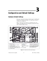
Accessing the Hardware Switches
The VXIpc 870 Series is housed in a metal enclosure comprised of a top
and bottom cover to improve EMC performance and to provide easy
handling. You need to remove the top cover to change many of the switch
and jumper settings. You must also remove the top cover to change the
amount of DRAM installed on the module.
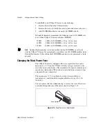
Remove the top cover by removing the screws that attach it to the module.
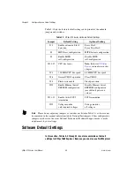
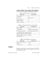
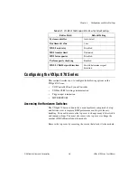
Table 3-7.
VXI-MXI-2 T&M Explorer MXI-2 Bus Tab Default Settings
Editor Field
Default Setting
System controller
Auto-detect
Bus timeout value
1 ms
MXI-2 auto retry
Disabled
MXI transfer limit
Unlimited
MXI fair requester
Disabled
Perform parity checking
Enabled
MXI-2 CLK10 signal direction
Switch determines signal
direction


