NI WSN-3212 User Guide and Specifications
18
ni.com
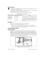
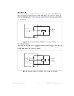
Connecting Thermocouples
Thermocouples attached to the NI WSN-3212 must be electrically isolated from the device digital I/O
ground (D GND) and earth ground.
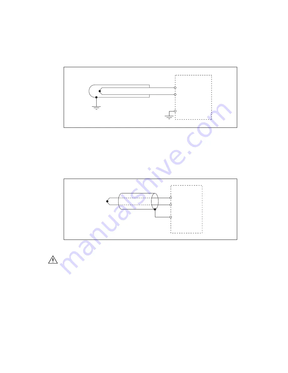
Figure 15.
Connecting an Isolated Thermocouple Probe
In Figure 15, the thermocouple junction is isolated from the outer metal probe sheath and even though
the sheath is earth grounded, the junction itself is isolated from earth ground. Many thermocouple
product manufacturers refer to this as an ungrounded thermocouple. Connect the thermocouple positive
lead to the TC+ terminal and the negative lead to the TC– terminal. Check the thermocouple
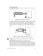
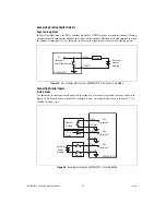
documentation or wire spool to determine the polarity of each lead. If using shielded thermocouple wire
with the shield not connected to earth ground, connect the shield to the COM terminal as shown in
Figure 16.
Figure 16.
Connecting an Ungrounded, Shielded Thermocouple Probe
If the shield connects to earth ground, leave the shield disconnected from the NI WSN-3212.
Caution
Connecting a non-isolated, earth grounded thermocouple causes corrupted temperature
measurements.
Determining Temperature Measurement Accuracy and Minimizing Errors
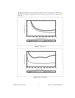
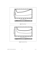
Temperature measurement errors depend, in part, on the thermocouple type, the temperature being
measured, the thermocouple accuracy, and the cold-junction temperature. Figures 17 through 21 shows
the typical and maximum errors for the different thermocouple types when used with the NI WSN-3212
over the full temperature range. The figures account for gain errors, offset errors, differential and integral
nonlinearity, quantization errors, noise errors, and isothermal errors. The figures do not account for the
thermocouple accuracy itself. Temperature gradients across the NI WSN-3212 terminals affect the
TC+
TC–
NI W
S
N-
3
212
I
s
ol
a
ted Thermoco
u
ple Probe
D GND
TC+
TC–
COM
NI W
S
N-
3
212
Thermoco
u
ple
S
hield


