©
National Instruments Corporation
5
NI WSN-3295 Outdoor IP Enclosure Installation Guide
Step 3: Connect Internal Cables
The NI WSN-3295 ships with a pre-installed IP-rated internal antenna cable and a RJ45 Ethernet cable,
which you need to connect to the NI 9792 WSN Real-Time Gateway once it is installed in the enclosure.
If you are using the second Ethernet connection on the NI 9792 Real-Time Gateway, refer to the
the Second Ethernet Connection
section.
Step 4: Assemble Glands
The NI WSN-3295 ships with two different insert sizes to use with the included gland shells. The
larger insert can accept cables with a diameter from 4–8 mm, while the smaller insert can
accommodate cables from 2–6 mm. For the larger 4–8 mm insert, NI recommends the Ethernet cable
(NI part number: 182219-05) and the power cord (NI part number: 780703-01) available from
ni.com
.
The NI WSN-3293 inserts accessory kit (NI Part Number: 195738-01) provides additional wiring
options and is available at
ni.com
. Table 1 shows the insert sizes.
Once the cable(s) and corresponding inserts are selected, complete the following steps to assemble the
cable glands:
1.
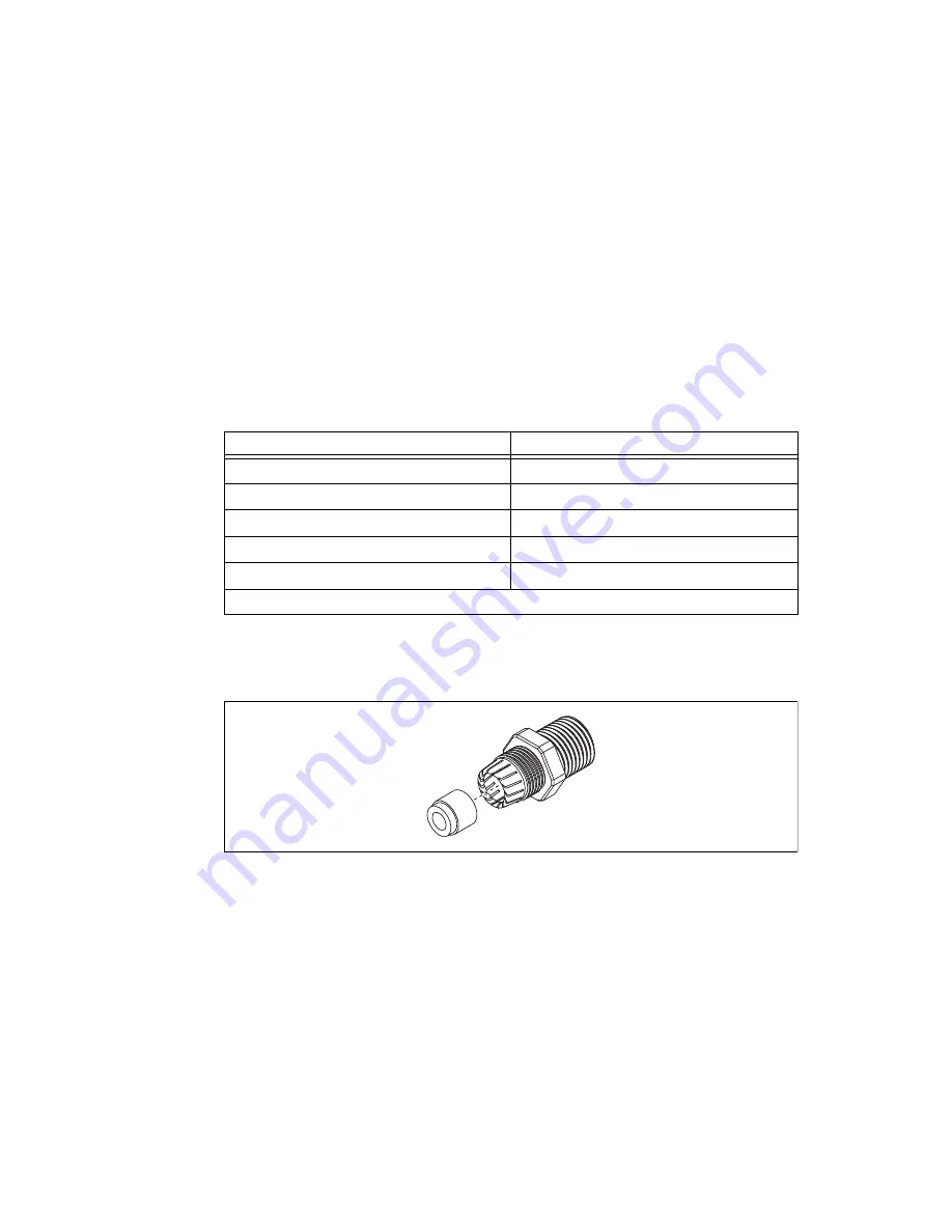
Assemble the selected inserts into the gland shell as shown in Figure 4.
Figure 4.
Assembling Insert into Gland Shell
2.
Loosely thread the included lock nut onto the gland shell as shown in Figure 7.
Table 1.
NI WSN-3293 Insert Sizes
Number of Holes
Wire Size
2
3 mm
4
1.7 mm
6
1.4 mm
10
1.4 mm
Solid Plug
*
—
*
The solid plug can be frozen and drilled to any size and configuration needed.


