background image

NI WSN-3295 Outdoor IP Enclosure Installation Guide

8

ni.com

Step 7: Install External Cables

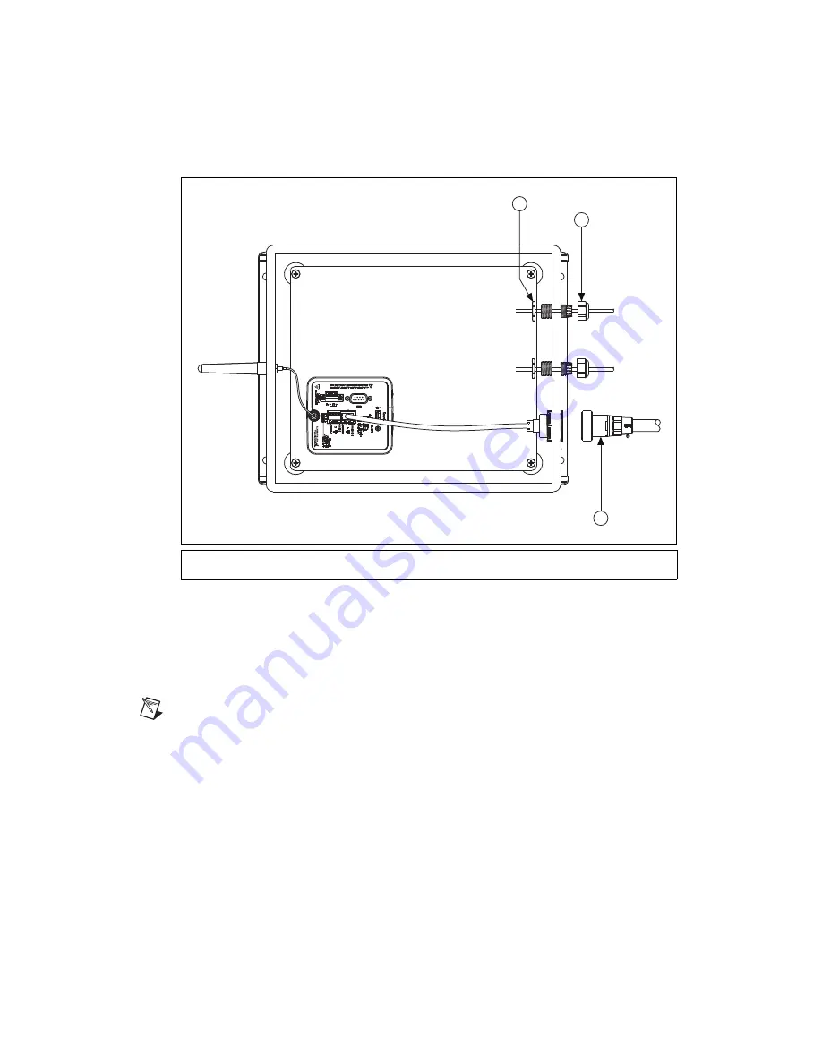
To install the external cables, refer to Figure 7 while completing the following steps:

Figure 7.  

External Cable Installation

1.

Tighten the lock nut to approximately 3.75 N · m (33.2 lb · in.) ensuring that the O-ring is pressed 
flat against the enclosure wall. 

2.

Tighten the outer compression nut to approximately 2.50 N · m (22.1 lb · in.) to seal the cable.

3.

Attach the external Ethernet field termination cable to the NI WSN-3295 Ethernet interface 
connector on the outside of the NI WSN-3295.

Note

A preassembled IP-rated 5 meter RJ45 Ethernet cable (NI part number: 196650-05) is 

available from 

ni.com

.

1

Lock Nut

2

Outer Compression Nut

3

Ethernet Field Termination Cable

1

2

3

Summary of Contents for WSN-3295

Page 1: ...2 device specifications refer to the NI 9792 WSN Real Time Gateway User Guide and Specifications available at ni com manuals Figure 1 shows the NI WSN 3295 outdoor IP enclosure components Figure 1 NI WSN 3295 Outdoor IP Enclosure Components Note You need a 1 and a 2 Phillips screwdriver to install the NI WSN 3295 1 Antenna IP Sleeve 2 2 4 GHz Antenna 3 Antenna IP Boot 4 Lock Nuts 5 Gland Shells 6 ...

Page 2: ...mp Ethernet plug Four 4 40 stainless steel screws to mount the NI 9792 Four 10 32 internal mounting plate screws pre installed One aluminum mounting plate pre installed One Ethernet field termination connector kit One Ethernet interface connector pre installed One Ethernet end cap One internal RJ45 Ethernet cable pre installed Dimensions Figure 2 shows the NI WSN 3295 dimensions Caution When mount...

Page 3: ...to set up and install the NI WSN 3295 Step 1 Unpack and Inspect the Kit Contents Remove the device from the package and inspect the device and kit contents Contact NI if the device appears damaged Do not install a damaged device or use kit contents that appear damaged 66 86 mm 2 633 in 143 5 mm 5 65 in 5 84 mm 0 23 in 343 15 mm 13 51 in 56 85 mm 2 238 in 180 59 mm 7 11 in 287 02 mm 11 3 in ...

Page 4: ...ernal mounting plate Remove the plate by unscrewing the 10 32 screws 3 Mount the NI 9792 WSN Real Time Gateway to the internal mounting plate using the included 4 40 screws Caution Using screws longer than 4 40 can damage the NI 9792 WSN Real Time Gateway 4 Reinstall the internal mounting plate with the attached NI 9792 WSN Real Time Gateway into the enclosure using the 10 32 screws as shown in Fi...

Page 5: ...aller insert can accommodate cables from 2 6 mm For the larger 4 8 mm insert NI recommends the Ethernet cable NI part number 182219 05 and the power cord NI part number 780703 01 available from ni com The NI WSN 3293 inserts accessory kit NI Part Number 195738 01 provides additional wiring options and is available at ni com Table 1 shows the insert sizes Once the cable s and corresponding inserts ...

Page 6: ...he following steps 1 On the outside of the enclosure place the antenna IP boot onto the external antenna connector with the smaller diameter hole out 2 Screw the antenna onto the external antenna connector until it bottoms out 3 Slide the IP sleeve down the antenna and over the IP boot until the IP sleeve touches the enclosure 1 IP Boot 2 Enclosure 3 External Antenna Connector 4 Antenna 5 IP Sleev...

Page 7: ...the NI WSN 3295 mounting hole dimensions which are molded on the enclosure back surface for convenience Tip NI recommends installing the NI 9792 WSN Real Time Gateway before mounting the NI WSN 3295 as shown in Figure 3 Figure 6 NI WSN 3295 Mounting Hole Dimensions and Locations 203 71 mm 8 02 in 324 36 mm 12 77 in 4X Ø 8 13 mm 0 32 in ...

Page 8: ...nsuring that the O ring is pressed flat against the enclosure wall 2 Tighten the outer compression nut to approximately 2 50 N m 22 1 lb in to seal the cable 3 Attach the external Ethernet field termination cable to the NI WSN 3295 Ethernet interface connector on the outside of the NI WSN 3295 Note A preassembled IP rated 5 meter RJ45 Ethernet cable NI part number 196650 05 is available from ni co...

Page 9: ...ation Guide Step 8 Attach the Cover The cover of the NI WSN 3295 is equipped with quick release latches not shown Tip You can prevent tampering with the enclosure contents by placing a lock through the holes in the quick release latches Figure 8 Attaching the NI WSN 3295 Cover ...

Page 10: ... 15 power supply panel mount to the NI WSN 3295 internal mounting plate NI does not recommend tapping the mounting plate There is enough room in the NI WSN 3295 for additional components if you want to add them Note that the tested thermal rating of 60 ºC external ambient applies when the enclosure contains the NI 9792 WSN Real Time Gateway with or without the PS 15 power supply NI does not guaran...

Page 11: ...ert the wires into the tunnels ensuring that they protrude all the way to the back of the plug 4 Finish by snapping the lid shut as shown in Figure 9 Table 2 IP Ratings First Number Protection Against Solid Objects Second Number Protection Against Water 0 No protection 0 No protection 1 Protects against objects greater than 50 mm 1 Protects against vertically dripping water 2 Protects against obje...

Page 12: ...l information refer to the NI and the Environment Web page at ni com environment This page contains the environmental regulations and directives with which NI complies as well as other environmental information not included in this document Waste Electrical and Electronic Equipment WEEE EU Customers At the end of the product life cycle all products must be sent to a WEEE recycling center For more ...

Reviews: