Ÿ
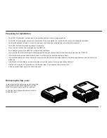
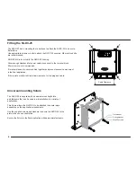
The NLDC-25 should be located close to the auxiliary battery for best voltage regulation.
Ÿ
The NLDC-25 can operate in harsh environments but it is best installed in a location that is cooler with adequate ventilation.
Ÿ
Avoid areas exposed to harsh or corrosive chemicals, excessive dust, extreme heat or mechanical movement.
Ÿ
The NLDC-25 can be installed vertically or horizontally.
Ÿ
Do not block or obstruct the cooling fins on the NLDC-25.
Ÿ
Allow clearance around the NLDC-25 for cables and ventilation.
Ÿ
It is normal for the NLDC-25 to get hot during operation, keep any objects that are heat-sensitive away from the NLDC-25.
Ÿ
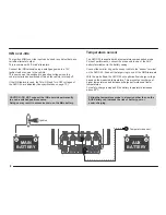
If the temperature compensation probe is used, it must be able to reach the auxiliary battery.
2
Ÿ
It is recommended to use 16mm cables for connections to the main and auxiliary batteries. Smaller gauge cables can be used for short
distances.
Ÿ
In-line fuses must be fitted in the positive cables close to the respective main and auxiliary batteries.
Ÿ
Use the common ground connections on the terminal block for all negative cable connections.
Ÿ
Use appropriate cable lugs for the cable size used.
Preparing for Installation
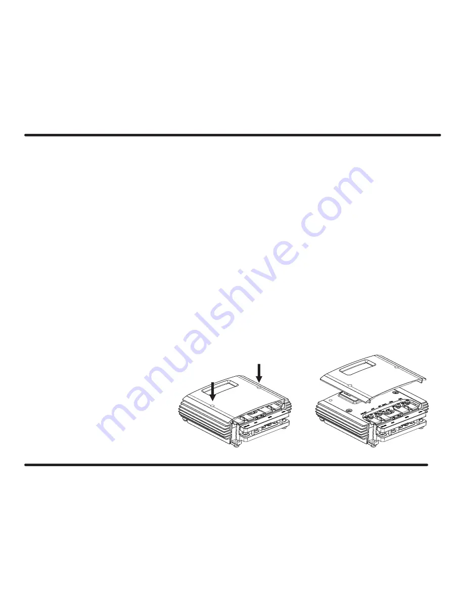
Removing the top cover
3
In order to select the battery type and to install the
temperature compensation & ignition over-ride
wires, the top cover will need to be removed.
Loosen the two screws as indicated in order to
release the cover.
Summary of Contents for NLDC-25
Page 1: ......
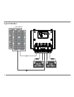
Page 8: ...Typical Installation FUSE FUSE SOLAR PANELS AUX BATTERY MAIN BATTERY 6 ...
Page 19: ......
Page 20: ......


