3 If a leak exists at this point in the disassembly of the meter, remove the calibration shaft O-ring Before reinserting the
O-ring, apply a light coat of silicon grease to it
4 Clean all parts
To gain access to the calibration ring, the straightening vane/nose cone must be removed See
“Removing the Magnet Carrier/Top Gear Set” on page 14
for instructions
To remove the calibration ring from the nose cone assembly:
1 Align the ring slots with the bayonets of the nose cone assembly (located on inner ring of calibration ring)
2 Carefully lift the calibration ring from the nose cone assembly
To reinstall the calibration mechanism, follow this procedure in reverse
CALIBRATION
LINKAGE
ARROW TIP
CAGE
INSERT
NOSE
CONE
TOP SIDE
SMALL HOLE WITH
CHAMFER UP
LARGE HOLE WITH
CHAMFER DOWN
INTO CAGE
THIS END
CALIBRATION RING
PIN
2", 3" and 4"
RETAINING RING
TRANSMISSION
GEAR
CALIBRATION DRIVE
PLATE
CAGE INSERT
(TOP VIEW)
PIN OF
CALIBRATION
RING
6"
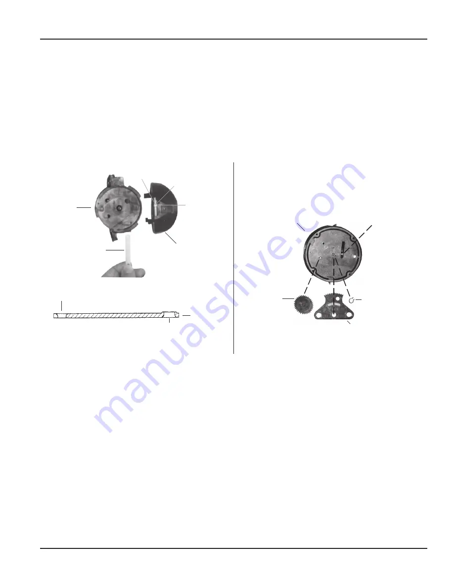
Figure 11: Calibration ring/linkage assemblies
Reassembling the Calibration Mechanism
1 Align the pin on the perimeter of the calibration ring with the arrow tip located on the nose cone assembly (see
)
2 For 2", 3" and 4" sizes, install the calibration linkage into the cage with the larger hole to engage the calibration ring
tab, with the side of chamfered edge of the hole towards the nose cone assembly (see
3 With the calibration linkage fully inserted to the cage stop, install the nose cone onto the cage and rotate it counter-
clockwise to engage the pin of the ring to the calibration linkage The hole of the calibration linkage has to be aligned
onto the calibration shaft, engaging it fully so that the calibration ring cannot vibrate during operation
4 Tighten the calibration shaft lock screw to securely hold the calibration ring in position
After servicing or replacing the calibration mechanism, check the accuracy and calibration according to the instructions in the
Recordall Turbo Series Meter User Manual
Servicing Parts and Assemblies
June 2016
RCS-UM-00076-EN-04
Page 15


