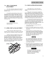
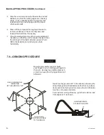
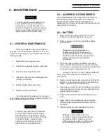
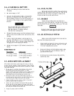
background image

HY70OM-8/99

12

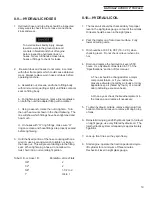
5.8—CHOKE

When starting a cold engine, pull the choke

control out to close the choke plate and allow a richer

fuel mixture to enter the engine.  After the engine starts,

push the choke control about half way in to keep the

partially closed. Push the choke control all the way in to

open the choke plate for normal operation after the

choke plate engine is properly warmed.  A warm engine

usually requires less choke to start.

5.9—THROTTLE LEVER

Push forward to increase engine speed, pull

back to decrease.

5.10—TRACTION PEDAL

The traction pedal operates the forward and reverse

direction and speed of the machine. By pushing the toe

of the pedal down, the forward speed is increased. By

pushing the heel of the pedal down the reverse speed is

increased. When the traction pedal is released the

machine will slow down and stop.

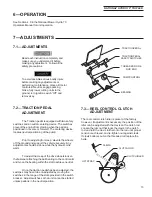
5.11—MOW AND LIFT TREADLE

Depress and hold the down pedal with left foot to

lower mowers. Reels will rotate if reel control lever is in

“ENGAGED” position. Depress and hold the up pedal to

raise mowers. Reels will stop if control lever is in

“ENGAGED” position when mowers are raised.

When operating the mow or lift pedal,

keep the pedal depressed until the

mowers have been completely lowered

or raised, and then release the pedal.

5.12—FREE-WHEELING VALVE

To permit moving the Hydro 70 without starting

the engine, a freewheeling device or tow valve has been

provided.

The valve is located under the left shield on the

front side of the vehicle. With the engine “OFF”, turn

knob to open valve and permit free-wheeling. Free-

wheeling valve must be closed during normal operation

or tractive effort will be severely reduced.

5.13—DROP/LIFT NEEDLE VALVE

A needle valve is located under the left shield on

the front side of the vehicle. By turning the needle valve

knob, the speed of drop and raising of the cutting units

can be adjusted as desired.

Familiarize yourself with the instrument

panel and the controls. Study the

instructions and learn to use the controls

correctly. Keep hands and feet away from

controls unless you intend to use them.

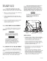
3.13  INTERLOCK SWITCHES

There are four interlock switches on your Hydro

70.  They are a safety precaution which will allow you to

start your mower only when the traction pedal is in

neutral, the reel control lever is in the disengaged

position and operator is seated on the tractor.  If you

are able to start your mower with these levers in any

other position, adjustment of the switches is required.

1. The neutral start switches are located under the

traction control pedal.

2. The reel control lever switch is located on the side of

the console and is activated by the reel lever.

3. The seat switch is located under the seat  and is

activated by the weight of the operator.

NOTE

Summary of Contents for HYDRO 70" TRIPLEX

Page 1: ...LEX NATIONALMOWERCO 700RaymondAve P O Box14299 St Paul Minnesota 55114 0299 U S A Phone 651 646 4079 Fax 651 646 2887 OWNER S MANUAL Includes Assembly Maintenance Parts Lists For Serial Numbers 1586 Up HYD70OM 8 99 ...

Page 2: ...ation relates corresponds to the relevant basic safety and health requirements of the Directive 89 392 EEC if applicable and to the requirements of other relevant Directives EN292 1 2 EN294 EN349 Title and or number and date of issue of the other Directives If applicable For the relevant implementation of the safety and health requirements mentioned in the directives the following standard s and o...

Page 3: ... for dangerous traffic when crossing or near roadways 11 Neverdirectthedischargeofmaterialfromoperatingreelstowardbystandersnorallowanyonenearthe mower during operation 12 Handle gasoline with CAUTION it is highly flammable a Use an approved gasoline container b Never fill the fuel tank indoors Wipe spilled gas immediately c Open garage doors to allow ventilation if engine is run inside exhaust fu...

Page 4: ... Ignition Switch 11 Hourmeter 11 Ammeter 11 ReelControl 11 Choke 12 ThrottleLever 12 TractionPedal 12 Mow and Lift Treadle 12 Free Wheeling Valve 12 Drop LiftNeedleValve 12 InterlockSwitches 12 Operation 13 Adjustments 13 TractionPedal 13 ReelControlClutch 13 14 Seat Switch 14 Height of Cut 14 Reel to Bedknife 15 Reel End Play 15 Backlapping Procedure 15 16 Grinding Procedure 16 Maintenance 17 Gen...

Page 5: ... consignee at the point of destination and filed with the transportation company that delivers the shipment Lubrication 20 Painting 20 BeltReplacement 20 21 CouplingAlignment 21 Storage 22 GeneralInstructions 22 Engine 22 Battery 22 Tractor 22 Tires 22 Starting After Storage 22 TroubleShootingGuide 23 Engine Will Not Start 23 Tractor Will Not Move 23 ReelNotTurning 23 Reel Will Not Cut 23 Lubricat...

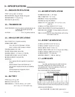
Page 6: ... TYPE Group U1 Type GT NOMINALVOLTAGE 12V DIMENSIONS L 7 3 4 19 68 cm x W 5 3 16 13 17 cm x H 7 5 16 18 5 cm 3 5 MOWERSPECIFICATIONS NUMBER AND SIZE 3 25 Reels REEL DIAMETER 7 17 8 cm BEARINGS TimkenTaperedRoller BLADES Six Alloy Steel Blades HEIGHT OF CUT Adjustable 1 2 to 2 1 3 cm to 5 08 cm OVERALL CUTTING WIDTH 70 177 8 cm HEIGHTADJUSTMENT RollerScrewAdjustment BEDKNIFE ADJUSTMENT Screw adjust...

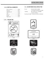
Page 7: ...W at 3200 rpm WEIGHT 528 kg 3 8 DISPOSALNUMBERS Petrol Lead Free 54104 Engine oil 54112 Fiberglassparts 57103 Tires 57502 Gear oil 54112 Grease 54202 Plastictanks 57127 3 9 NOISEEMISSION VIBRATION Sound Operator Position 88 dBA Sound Power Level LwA 106 dBA Vibration Max Vibration 57 7 m s2 RMS Location Left Hand Operating Condition Engine rpm 3200 Unit stationary 3 10 TRANSFERS ...

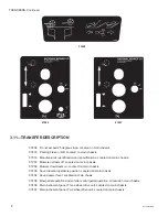
Page 8: ...ain chassis 07257 Mowers up reels off Located on main chassis 07256 Mowers down reels on Located on main chassis 07405 Sound level at operators position Located on main chassis 07404 Sound power level Located on main chasis 07408 Mow pedal operation and vehicle motion pedal operation Located on main chassis 07409 Main instrument panel Three wheel drive unit Located on main chassis 07407 Main instr...

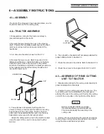
Page 9: ...the seat slider which is assembled to the seat onto the seat base plate and secure with locknuts provided Attach the safety switch wires to the switch located under the seat Wires can be connected to either terminal HANDLEBAR KEY COVER 6 Tires should be checked and if necessary adjusted for proper inflation Refer to Section 3 3 7 Check the oil level in the oil tank Refer to Section 8 10 8 Check th...

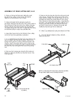
Page 10: ...reinsert the fastener provided thru the bushing into the hole on the cutting unit 8 Remove the tie wraps securing the lift chains and attach the chains to the lift arm under the tractor One chain per side ASSEMBLY OF REAR CUTTING UNIT Con t PIVOT BRACKET PULL ROD FRAME PUSHARM SPRING SLEEVE PUSH ARM SHAFT 9 Remove the tie wrap attaching the cutting unit belts to the tractor Position the cutting un...

Page 11: ...aft to the mowers 5 4 IGNITION SWITCH The reel control lever must be in the disengage position and the traction control pedal is in the neutral position before starting engine Insert key in switch turn clockwise as far as it will go to start engine then release a Do not hold key in ON position more than 30 seconds at a time b Key should be removed when tractor is not in use to prevent unauthorized...

Page 12: ... WHEELINGVALVE To permit moving the Hydro 70 without starting the engine a freewheeling device or tow valve has been provided The valve is located under the left shield on the front side of the vehicle With the engine OFF turn knob to open valve and permit free wheeling Free wheeling valve must be closed during normal operation or tractive effort will be severely reduced 5 13 DROP LIFTNEEDLEVALVE ...

Page 13: ...oil is warm To adjust the creep of the drive wheels loosen the fastener attaching the ball bearing to the control arm and move the bearing within the slot to achieve neutral Once the traction pedal has been adjusted the switches may have to be re adjusted by moving the switches in the range of the slots provided in the switch bracket Adjust switches so that unit cannot be started unless pedal is i...

Page 14: ... will be uniform cutting on the entire width of the mower Do not adjust rollers by sight After loosening adjusting nuts on each side of the reel assembly place a gauge plate under the bedknife and roller measuring the distance between bedknife cutting edge and the rollers Adjust front and rear rollers equally and insure that the bottom of the bedknife is parallel with the ground After height of cu...

Page 15: ...pound such as Pinhigh Prices grit ranges and ordering information are available by calling a toll free phone number 1 800 422 4748 Pre mixed compound saves the time required to mix eliminates the waste of abrasive rinses off easily with water and is available in all grit ranges from coarse to extra fine This procedure should be performed when the reel blades and bed knife become slightly rounded a...

Page 16: ...he reels Use approved safety glasses to protect tour eyes from flying particles and abrasives 5 Stop the reel and examine both bed knife and reel blades to see that the cutting edges are uniformly sharp If not gradually tighten hex adjuster and repeat Step 4 on previous page until the proper sharpnessresults 6 Rinse off the compound thoroughly with water to remove all abrasive Check for sharpness ...

Page 17: ...sition of parts when disassembling Clean and lubricate individual parts and components as required 8 3 BATTERY 1 Make certain the ignition switch is in the Off position and the keys have been removed 2 Refer to Section 3 4 in this manual for battery specifications Always wear protective glasses or goggles and protective clothing when working with batteries You must follow the battery manufacturer ...

Page 18: ... hours thereafter Engine replacement parts should be ordered through your local Briggs Stratton dealer 8 8 ELECTRICALSYSTEM Make certain all terminals and connections are kept clean and properly secured 1 Check switches regularly to be sure they are kept clean and operating correctly See 7 2 7 3 and 7 4 in the Adjustments section 2 Keep wire harness and all individual wires away from moving parts ...

Page 19: ...fitting seal When tightening a hose do not allow it to twist hold it in a normal straight portion Tube O D or Hose I D Rotate No of Hex Flats 3 8 2 1 2 2 5 8 1 1 2 to 2 1 3 4 to 1 8 10 HYDRAULICOIL 1 The reservoir should be checked daily for proper level in the sight glass gauge on rear of the oil tank Oil level should be seen in the sight glass 2 Park the tractor on a flat or level surface Fully ...

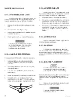
Page 20: ... to shaft 8 13 JUMPERCABLES Before attempting to jump the battery check the condition of the battery check the water level and refer to the battery manufacturer s instructions 1 Stop the engine on vehicle with good battery 2 Connect one jumper cable to positive terminal on good battery Connect other end of the jumper cable to the positive terminal on the dead battery 3 Connect one jumper cable to ...

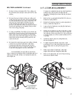
Page 21: ...T REPLACEMENT Continued 1 Gently roll the pivot bracket off of the cutting unit Now the belts can easily be removed from the reel pulleys 2 Remove the top two bolts on the rear cutting unit right side only pivot bracket Noting this bracket is under spring pressure Loosen the bottom bolt and use it as a pivot point Roll back the pivot bracket allowing the spring pressure and belt tension to be rele...

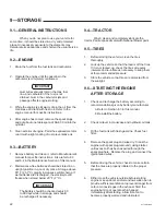
Page 22: ...low 20 F 7 C The battery should be checked every 60 to 90 days while in storage and should be recharged if necessary 9 4 TRACTOR Wash clean and completely lubricate the tractor Paint exposed metal with National Mower paint 9 5 TIRES 1 Before storing the vehicle clean the tires thoroughly 2 Jack up the vehicle so that the load is off the tires If it is not jacked up check the tires at regular inter...

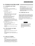
Page 23: ... control mechanism to assure complete attachment of alllinkages 10 3 REEL NOT TURNING Check for debris jammed between reel and bedknife Check for proper belt tension Tensioning on belts for countershaft to reel is non adjustable Check the condition of the slider shaft under spring of the push and pull arms for free movement if necessary clean shaft and apply grease to mating surfaces If slippage s...

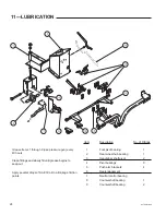
Page 24: ...ease begins to seep out Apply several drops of SAE 30 oil to all linkage friction points Item Description No of Fittings 1 Fork pivot bearing 1 2 Rear wheel hub bearing 1 3 Handle bar shaft pivot 2 4 Pivotbearings 9 5 Push arm brackets 4 6 Reelengagement 7 Neutral control bearing 8 Countershaftbearing 1 9 Countershaftbearing 2 ...

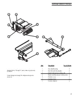
Page 25: ...rs Clean fittings and slowly fill until grease begins to seep out Item Description No of Fittings 1 Reel shaft bearing 2 2 Reel to bed knife adjuster 2 3 Roller bearing per cutting unit 4 4 Roller adj bracket per cutting unit 4 5 Pull arm rear 2 6 Pull arm front 4 7 Pull arm bracket 4 ...

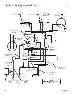
Page 26: ... SOLENOID 07057 SOLENOIDWIRE 07384 30AMPFUSE TRACTION PEDAL SWITCH 302533 WIREHARNESS 07328 TOGGLE SWITCH 07386 SOLENOID VALVE 07395 GROUND WIRE 07385 SOLENOID WIRE 07383 STARTER ENGINE REGULATOR ANTIAFTER FIRE SOLENOID STOP SWITCH STARTER WIRE 07104 NOTE THIRDWHEELASSIST MODELONLY Red Yellow Blue White White White Black Red Yellow White Yellow Orange Black Blue Red Yellow ...

Page 27: ... number 2 Model Number and Serial Number plate located on the main frame between the oil tank and the fuel tank 3 Part Number it is recommended that the correct number be verified with a current Master Price List 4 The full Description of the part 5 Quantity desired quantity shown is the total number of parts con tained in the particular view shown IfthePartNumberandtheDescriptionofyourorderdonota...

Page 28: ...HY70OM 8 99 28 ...

Page 29: ...302067 SPACER Rear Wheel 1 19 302069 AXLE Rear Wheel 1 _ _ _ _ _ _ _ _ _ _ _ _ _ _ _ _ _ _ _ _ _ _ _ _ _ _ _ _ _ _ _ _ _ _ _ _ _ _ _ _ _ _ _ _ _ _ _ _ _ _ _ _ _ _ _ _ _ _ _ _ _ _ _ _ _ _ _ _ _ _ _ _ _ _ _ _ _ _ _ _ _ _ _ _ _ _ _ _ _ _ _ _ _ _ _ _ _ _ _ _ _ _ _ _ _ _ _ _ _ _ _ _ _ _ _ _ _ _ _ _ _ _ _ _ _ _ _ _ _ _ _ _ _ _ _ _ _ _ _ _ _ _ _ _ _ _ _ _ _ _ _ _ _ _ _ _ _ _ _ _ _ _ _ _ _ _ _ _ _ _ _ _ _...

Page 30: ...HY70OM 8 99 30 ...

Page 31: ..._ _ _ _ _ _ _ _ _ _ _ _ _ _ _ _ _ _ _ _ _ _ _ _ _ _ _ _ _ _ _ _ _ _ _ _ _ _ _ _ _ _ _ _ _ _ _ _ _ _ _ _ _ _ _ _ _ _ _ _ _ _ _ _ _ _ _ _ _ _ _ _ _ _ _ _ _ _ _ _ _ _ _ _ _ _ _ _ _ _ _ _ _ _ _ _ _ _ _ _ _ _ _ _ _ _ _ _ _ _ _ _ _ _ _ _ _ _ _ _ _ _ _ _ _ _ _ _ _ _ _ _ _ _ _ _ _ _ _ _ _ _ _ _ _ _ _ _ _ _ _ _ _ _ _ _ _ _ _ _ _ _ _ _ _ _ _ _ _ _ _ _ _ _ _ _ _ _ _ _ _ _ _ _ _ _ _ _ _ _ _ _ _ _ _ _ _ _ _ _ ...

Page 32: ...HY70OM 8 99 32 ...

Page 33: ... _ _ _ _ _ _ _ _ _ _ _ _ _ _ _ _ _ _ _ _ _ _ _ _ _ _ _ _ _ _ _ _ _ _ _ _ _ _ _ _ _ _ _ _ _ _ _ _ _ _ _ _ _ _ _ _ _ _ _ _ _ _ _ _ _ _ _ _ _ _ _ _ _ _ _ _ _ _ _ _ _ _ _ _ _ _ _ _ _ _ _ _ _ _ _ _ _ _ _ _ _ _ _ _ _ _ _ _ _ _ _ _ _ _ _ _ _ _ _ _ _ _ _ _ _ _ _ _ _ _ _ _ _ _ _ _ _ _ _ _ _ _ _ _ _ _ _ _ _ _ _ _ _ _ _ _ _ _ _ _ _ _ _ _ _ _ _ _ _ _ _ _ _ _ _ _ _ _ _ _ _ _ _ _ _ _ _ _ _ _ _ _ _ _ _ _ _ _ _ _...

Page 34: ...HY70OM 8 99 34 ...

Page 35: ... _ _ _ _ _ _ _ _ _ _ _ _ _ _ _ _ _ _ _ _ _ _ _ _ _ _ _ _ _ _ _ _ _ _ _ _ _ _ _ _ _ _ _ _ _ _ _ _ _ _ _ _ _ _ _ _ _ _ _ _ _ _ _ _ _ _ _ _ _ _ _ _ _ _ _ _ _ _ _ _ _ _ _ _ _ _ _ _ _ _ _ _ _ _ _ _ _ _ _ _ _ _ _ _ _ _ _ _ _ _ _ _ _ _ _ _ _ _ _ _ _ _ _ _ _ _ _ _ _ _ _ _ _ _ _ _ _ _ _ _ _ _ _ _ _ _ _ _ _ _ _ _ _ _ _ _ _ _ _ _ _ _ _ _ _ _ _ _ _ _ _ _ _ _ _ _ _ _ _ _ _ _ _ _ _ _ _ _ _ _ _ _ _ _ _ _ _ _ _ _...

Page 36: ...HY70OM 8 99 36 ...

Page 37: ..._ _ _ _ _ _ _ _ _ _ _ _ _ _ _ _ _ _ _ _ _ _ _ _ _ _ _ _ _ _ _ _ _ _ _ _ _ _ _ _ _ _ _ _ _ _ _ _ _ _ _ _ _ _ _ _ _ _ _ _ _ _ _ _ _ _ _ _ _ _ _ _ _ _ _ _ _ _ _ _ _ _ _ _ _ _ _ _ _ _ _ _ _ _ _ _ _ _ _ _ _ _ _ _ _ _ _ _ _ _ _ _ _ _ _ _ _ _ _ _ _ _ _ _ _ _ _ _ _ _ _ _ _ _ _ _ _ _ _ _ _ _ _ _ _ _ _ _ _ _ _ _ _ _ _ _ _ _ _ _ _ _ _ _ _ _ _ _ _ _ _ _ _ _ _ _ _ _ _ _ _ _ _ _ _ _ _ _ _ _ _ _ _ _ _ _ _ _ _ _ ...

Page 38: ...HY70OM 8 99 38 ...

Page 39: ... _ _ _ _ _ _ _ _ _ _ _ _ _ _ _ _ _ _ _ _ _ _ _ _ _ _ _ _ _ _ _ _ _ _ _ _ _ _ _ _ _ _ _ _ _ _ _ _ _ _ _ _ _ _ _ _ _ _ _ _ _ _ _ _ _ _ _ _ _ _ _ _ _ _ _ _ _ _ _ _ _ _ _ _ _ _ _ _ _ _ _ _ _ _ _ _ _ _ _ _ _ _ _ _ _ _ _ _ _ _ _ _ _ _ _ _ _ _ _ _ _ _ _ _ _ _ _ _ _ _ _ _ _ _ _ _ _ _ _ _ _ _ _ _ _ _ _ _ _ _ _ _ _ _ _ _ _ _ _ _ _ _ _ _ _ _ _ _ _ _ _ _ _ _ _ _ _ _ _ _ _ _ _ _ _ _ _ _ _ _ _ _ _ _ _ _ _ _ _ _...

Page 40: ...HY70OM 8 99 40 ...
Page 41: ... _ _ _ _ _ _ _ _ _ _ _ _ _ _ _ _ _ _ _ _ _ _ _ _ _ _ _ _ _ _ _ _ _ _ _ _ _ _ _ _ _ _ _ _ _ _ _ _ _ _ _ _ _ _ _ _ _ _ _ _ _ _ _ _ _ _ _ _ _ _ _ _ _ _ _ _ _ _ _ _ _ _ _ _ _ _ _ _ _ _ _ _ _ _ _ _ _ _ _ _ _ _ _ _ _ _ _ _ _ _ _ _ _ _ _ _ _ _ _ _ _ _ _ _ _ _ _ _ _ _ _ _ _ _ _ _ _ _ _ _ _ _ _ _ _ _ _ _ _ _ _ _ _ _ _ _ _ _ _ _ _ _ _ _ _ _ _ _ _ _ _ _ _ _ _ _ _ _ _ _ _ _ _ _ _ _ _ _ _ _ _ _ _ _ _ _ _ _ _ _...

Page 42: ...HY70OM 8 99 42 WHEEL MOTOR PUMP FILTER LIFT CYLINDER TANK NEEDLE VALVE LIFT VALVE WHEEL MOTOR REAR WHEEL MOTOR ...

Page 43: ...E BlocktoBulkhead 1 19 07379 LINE BlocktoBulkhead 1 20 07382 HOSE BulkheadtoBulkhead 2 21 07381 HOSE Rear Motor 2 22 302688 SLEEVE Hoses 1 __________________________________________________________________________________________________________________________________________________________ __________________________________________________________________________________________________________...

Page 44: ...HY70OM 8 99 44 WHEEL MOTOR FILTER PUMP LIFT CYLINDER TANK NEEDLE VALVE LIFT VALVE WHEEL MOTOR REAR WHEEL MOTOR ...

Page 45: ... _ _ _ _ _ _ _ _ _ _ _ _ _ _ _ _ _ _ _ _ _ _ _ _ _ _ _ _ _ _ _ _ _ _ _ _ _ _ _ _ _ _ _ _ _ _ _ _ _ _ _ _ _ _ _ _ _ _ _ _ _ _ _ _ _ _ _ _ _ _ _ _ _ _ _ _ _ _ _ _ _ _ _ _ _ _ _ _ _ _ _ _ _ _ _ _ _ _ _ _ _ _ _ _ _ _ _ _ _ _ _ _ _ _ _ _ _ _ _ _ _ _ _ _ _ _ _ _ _ _ _ _ _ _ _ _ _ _ _ _ _ _ _ _ _ _ _ _ _ _ _ _ _ _ _ _ _ _ _ _ _ _ _ _ _ _ _ _ _ _ _ _ _ _ _ _ _ _ _ _ _ _ _ _ _ _ _ _ _ _ _ _ _ _ _ _ _ _ _ _...

Page 46: ...__________________________________________________________________________________________________________________________ Item Description Part No Qty BASKET ASSEMBLY Kit No 070001 BELT TOOL KIT KIt No 070008 1 07337 BASKET Rear 1 2 302526 HANGER 1 3 302562 SHIELD RearCuttingUnit 1 4 302527 BRACKET Basket 1 5 302528 BRACKET Basket 1 6 302390 SHIELD FrontThrow 2 7 302529 BRACKET Basket 1 8 07338 B...

Page 47: ...No 070009 Qty _ _ _ _ _ _ _ _ _ _ _ _ _ _ _ _ _ _ _ _ _ _ _ _ _ _ _ _ _ _ _ _ _ _ _ _ _ _ _ _ _ _ _ _ _ _ _ _ _ _ _ _ _ _ _ _ _ _ _ _ _ _ _ _ _ _ _ _ _ _ _ _ _ _ _ _ _ _ _ _ _ _ _ _ _ _ _ _ _ _ _ _ _ _ _ _ _ _ _ _ _ _ _ _ _ _ _ _ _ _ _ _ _ _ _ _ _ _ _ _ _ _ _ _ _ _ _ _ _ _ _ _ _ _ _ _ _ _ _ _ _ _ _ _ _ _ _ Qty _ _ _ _ _ _ _ _ _ _ _ _ _ _ _ _ _ _ _ _ _ _ _ _ _ _ _ _ _ _ _ _ _ _ _ _ _ _ _ _ _ _ _ _ ...

Page 48: ... Qty _ _ _ _ _ _ _ _ _ _ _ _ _ _ _ _ _ _ _ _ _ _ _ _ _ _ _ _ _ _ _ _ _ _ _ _ _ _ _ _ _ _ _ _ _ _ _ _ _ _ _ _ _ _ _ _ _ _ _ _ _ _ _ _ _ _ _ _ _ _ _ _ _ _ _ _ _ _ _ _ _ _ _ _ _ _ _ _ _ _ _ _ _ _ _ _ _ _ _ _ _ _ _ _ _ _ _ _ _ _ _ _ _ _ _ _ _ _ _ _ _ _ _ _ _ _ _ _ _ _ _ _ _ _ _ _ _ _ _ _ _ _ _ _ _ _ _ Qty _ _ _ _ _ _ _ _ _ _ _ _ _ _ _ _ _ _ _ _ _ _ _ _ _ _ _ _ _ _ _ _ _ _ _ _ _ _ _ _ _ _ _ _ _ _ _ _ _...

Page 49: ... _ _ _ _ _ _ _ _ _ _ _ _ _ _ _ _ _ _ _ _ _ _ _ _ _ _ _ _ _ _ _ _ _ _ _ _ _ _ _ _ _ _ _ _ _ _ _ _ _ _ _ _ _ _ _ _ _ _ _ _ _ _ _ _ _ _ _ _ _ _ _ _ _ _ _ _ _ _ _ _ _ _ _ _ _ _ _ _ _ _ _ _ _ _ _ _ _ _ _ _ _ _ _ _ _ _ _ _ _ _ _ _ _ _ _ _ _ _ _ _ _ _ _ _ _ _ _ _ _ _ _ _ _ _ _ _ _ _ _ _ Qty _ _ _ _ _ _ _ _ _ _ _ _ _ _ _ _ _ _ _ _ _ _ _ _ _ _ _ _ _ _ _ _ _ _ _ _ _ _ _ _ _ _ _ _ _ _ _ _ _ _ _ _ _ _ _ _ _ _...

Page 50: ... _ _ _ _ _ _ _ _ _ _ _ _ _ _ _ _ _ _ _ _ _ _ _ _ _ _ _ Qty _ _ _ _ _ _ _ _ _ _ _ _ _ _ _ _ _ _ _ _ _ _ _ _ _ _ _ _ _ _ _ _ _ _ _ _ _ _ _ _ _ _ _ _ _ _ _ _ _ _ _ _ _ _ _ _ _ _ _ _ _ _ _ _ _ _ _ _ _ _ _ _ _ _ _ _ _ _ _ _ _ _ _ _ _ _ _ _ _ _ _ _ _ _ _ _ _ _ _ _ _ _ _ _ _ _ _ _ _ _ _ _ _ _ _ _ _ _ _ _ _ _ _ _ _ _ _ _ _ _ _ _ _ _ _ _ _ Item Part No Description Description Item Part No VALVE BLOCK Part ...

Page 51: ...es enginepartsortireswhicharecovered under separate warranties furnished by their manufacture or supplier All service under this warranty will be furnished and performed by our Factory Authorized Service Stations THERE IS NO OTHER EXPRESS WARRANTY IMPLIEDWARRANTIES INCLUDINGTHOSEOFMERCHANTABILITYAND FITNESS FOR A PARTICULAR PURPOSE ARE LIMITED TO ONE YEAR FROM PURCHASE OR 45 DAYS IF THE PRODUCT IS...

Reviews: