OPERATING PROCEDURES
100 Avon Street, P.O. Box 1547
Charlottesville, VA 22902
Tel: 434-295-9126 Tech Support: 800-247-9796 Fax: 888-239-0778
Revision: 11/98 Page -
13
-
NATIONAL
INCORPORATED
It is suggested that the operator now run additional test lenses, changing the bevel
placement and size. The operator can also experiment with the three control features (
Finish
Only
,
Rimless
, and
Pause
), to gain a familiarity with the edger’s operating sequence and
controls.
BEVEL PLACEMENT SYSTEMS - TWO ALTERNATIVES:
The edger is supplied with two methods of controlling the placement of the bevel (or
groove) on the periphery of the lens.
Front Curve Tracking Bevel System In Place
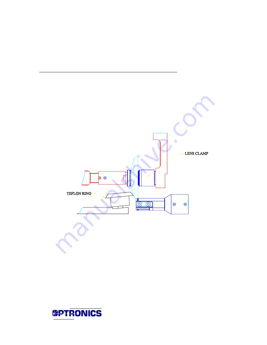
The bevel guide wheel tracking system uses a Teflon wheel, which tracks the front
curve of the lens (
Fig. 4
). The position of the wheel is controlled by the knob on the right
side of the edger.
Figure 4 – Front Curve Tracking System in Place
It is important that the edge of the Teflon guide wheel be concentric within a few
thousandths of an inch, as the bevel, groove and facet placements on the lens are extremely
responsive to the position of the wheel. It is advisable to occasionally run your finger around
the wheel edge to dislodge any particles and check for wear. See the Maintenance section for
instructions on changing the wheel.
Note:
The position of the bevel guide wheel is factory-set at the beveling position. When
running faceted lenses, the wheel must be raised away from the cutter to allow clearance for
the top of the ramps. (Refer to the Faceting procedures.)


