Page 8
ASSEMBLY (continued)
FOR SHIPPING, WHEEL ADJUSTMENT PINS ARE NOT INSERTED CORRECTLY THROUGH
HANDLE FRAME.
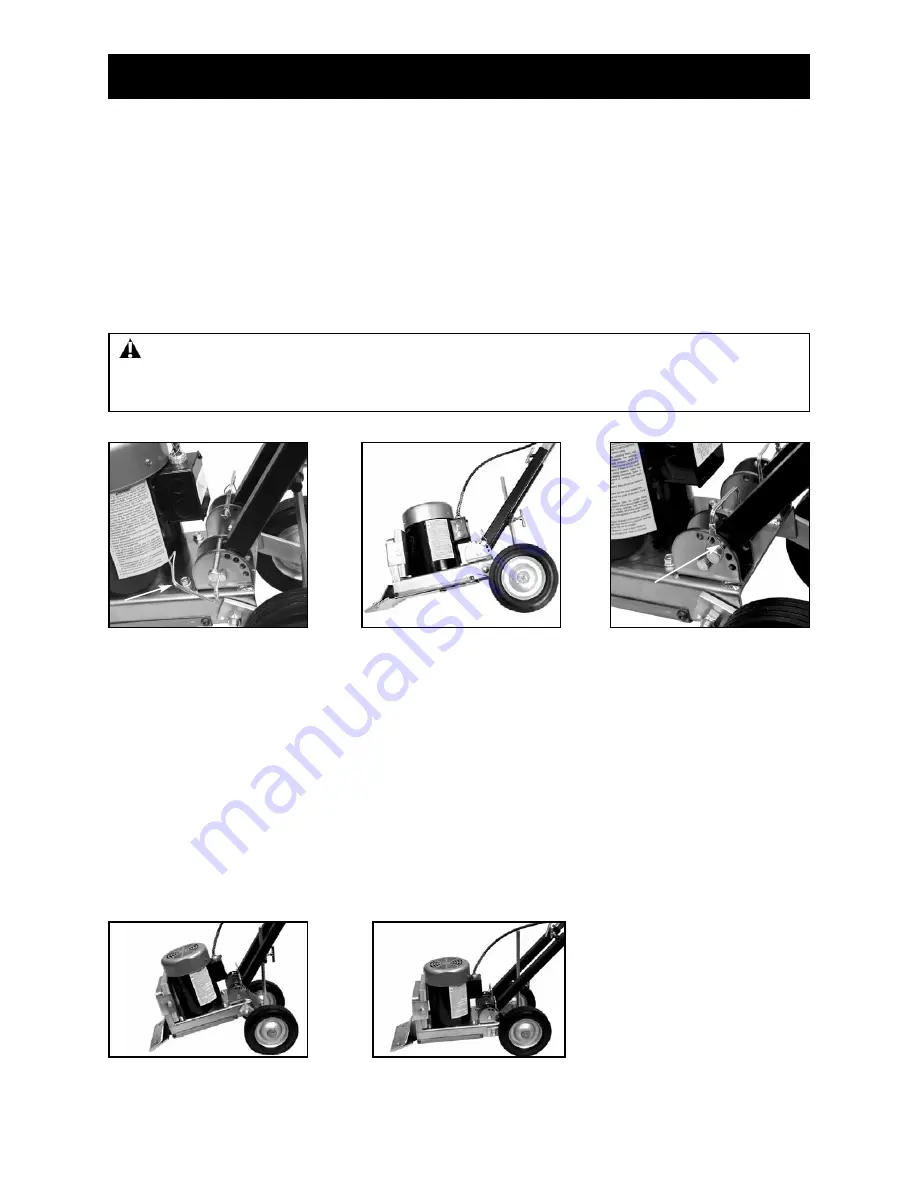
1. Remove handle adjustment pins (See Figure A). It may be necessary to maneuver handle so it is not
touching the handle adjustment pins. OR, lay machine onto side (See Figure B).
2. Adjust handle to proper angle (center hole is the most common).
3. Insert handle adjustment pins into desired hole (See Figure C) and secure.
WARNING:
Do not operate machine around excessive moisture areas, such as abatement work
and flooded pool areas without GFI wall plug (stock #530 Circuit Guard). Failure to do so could cause
damage in machine or injury to operator.
Figure A
Figure B
Figure C
GENERAL OPERATION
Remove handle
adjustment pins
Insert pin into
desired hole
WHEEL ADJUSTMENT
Adjusting wheel angle will change the blade angle to the floor. A steep wheel angle is recommended on
hard tear-outs such as tile over concrete (See Figure D). A low wheel angle is recommended on vinyl
tear-outs and plywood floors (See Figure E).
1. Loosen T-Bolt on adjustment T-bar.
2. Adjust wheels (by handle) to preferred angle.
3. Securely tighten T-bolt on adjustment T-bar.
NOTE:
Adjustment by trial at the beginning of a job will give optimum performance.
Figure D
Figure E
Steep Angle
Low Angle
Lay unit on side


