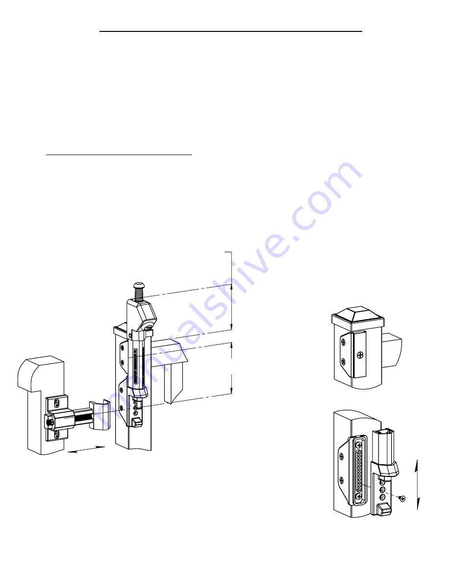
FIGURE 3
ADJUSTABLE
MAX = 5.00"
MIN = 2.00"
(Check Local Codes)
MIN = 2.00"
MAX = 5.00"
CL of Keeper
Bracket
CL of Upper
Bracket
FENCE
GATE
Top of Latch
Top of Fence
FIGURE 1
ADJUSTABLE
FIGURE 2
STEP-1
Determine mounting height based upon local code
requirements.
STEP-2
Install Upper Bracket using (3) self-drilling flat head
screws, as near to the top of the fence post as possible
(Fig 2).
STEP-3
Install Lower Bracket:
1.) Align the rear groove in the Main Latch Body
with the tab in the Upper Bracket and slide the latch
into position. Using a measuring device, locate the
top of the latch at the proper height (Fig 1).
"REFER TO ALL LOCAL BUILDING CODES
"
2.) Temporarily insert the Bottom Bracket and align
the holes with the (3) countersunk holes at the
bottom of the Main Body (Fig 3). With the latch at
the proper height, mark the location on the post.
3.) Remove main body and attach the lower
bracket with the supplied self-drilling screws: (2) flat
head and (2) pan head.
STEP-4
Install Main Latch Body
1.) Re-install main body as described in STEP 3 by
sliding over both the Upper and Lower Brackets.
2.) Align the holes of the Latch and the Bottom Bracket,
making sure that the overall latch height is maintained,
and secure with (1) #8 flat head screw (Fig 3).
STEP-5
Install "Keeper"
1.) With gate closed, position keeper and align with
Main Latch Body. Secure Keeper to gate with (4) self-
drilling pan head screws provided.
STEP-6
Final Adjustments
If any final adjustments are needed, use the Horizontal
adjustment screw in the Keeper assembly, and or the
Vertical adjustment holes located in the Lower Bracket.
PROTECTOR INSTALLATION PROCEEDURE
®


