ZephIR user manual QP1009-582 v2
© Natural Power 2008
10
th
June 2008
Page 14
Battery Pod and Tripod
Configuration
ZephIR comprises three core elements, the Optics Pod, the
Electronics Pod and the Battery Pod. Each pod is transported
separately and is integrated on site.
WARNING: The unit is very heavy and care must be taken
when moving, installing and dismantling.
Configuration of the battery pod and the system tripod is
a critical component of the ZephIR system setup. Ensure
that when there is more than one ‘PinHead’ allen screw the
screws are loosened / tightened sequentially in stages.
1.
Selecting the specific location
To achieve optimum system performance, the system must
be aligned in a vertical orientation and configured in a
nominal north direction. ZephIR is mounted on three tripod
legs which occupy a nominal surface area of 1m diameter.
The system should be located on a piece of ground with
no obstacles (trees, buildings) in close proximity. Ensure
that ZephIR is deployed on semi-firm ground. Use ‘spreader
plates’ on each foot if required.
2.
Tripod feet configuration
The integrated Tripod arrangement supplied with ZephIR
includes a load spreading foot, suitable for semi-firm
ground.
Prior to the attachment of the Tripod legs, the feet should be
secured. To do this, the user must undo the ‘PinHead’ allen
screw located on the base of the Tripod leg and insert the
foot oriented with the foot orientated to touch the ground..
The ‘PinHead’ allen screw can then be re-tightened.
3.
Removing the batteries
Backup batteries included with ZephIR contribute to 44kg of
weight in the system. Prior to movement of the battery Pod,
it is recommended that the batteries are removed and re-
inserted as part of the configuration process. Disconnecting
the batteries in this way also ensures that the batteries are
not discharged when not in use for a large period of time.
4.
Ground Anchor
ZephIR includes a ground anchoring point at the base of
the Battery Pod.
Depending on the specifics of the site location, a ground
anchor should be inserted into the ground with an
appropriate attachment which can be secured to the base
of the Battery Pod.
5.
Battery Pod alignment
On final selection of the site, it is important that the
Battery Pod is located such that the system points in a
north direction. Accurate north alignment is achieved using
a compass.
The battery pod includes a directional arrow to aid alignment
and this should point north.
6.
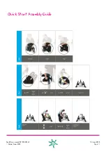
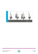
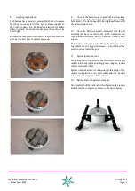
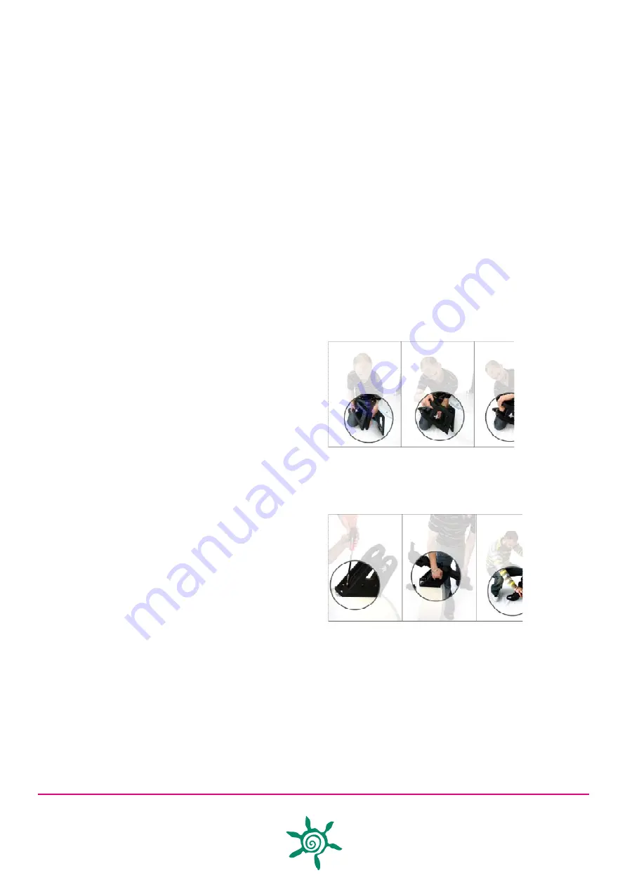
Tripod bracket / leg attachment
Each bracket requires attachment to the Battery Pod, each
leg hooks onto the pod as shown below and is secured
using the ‘PinHead’ allen screws provided.
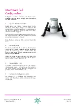
Each Tripod leg requires insertion into the bracket as shown
below;
7.
Levelling the Battery Pod
Once system legs are attached, the Tripod legs can be
utilised to level the Battery Pod. Each leg has several
‘PinHead’ allen screws and a hand screw. For ease of
adjustment, the ‘PinHead’ allen screws and the hand screw
should be released to allow the leg to be adjusted. Once
levelled, usingthe supplied spirit level, on all three legs, all
the ‘PinHead’ allen screws and hand screw on each leg can
be tightened to ensure that the equipment does not move
over time.

