ZephIR user manual QP1009-582 v2
© Natural Power 2008
10
th
June 2008
Page 18
Met Station and Met
Mast Configuration
Configuration of the Met Station and Mast should not be
undertaken until the optics pod, electronics pod, battery
pod and tripod configuration has been completed.
1.
Alignment of the Met Mast
Prior to the attachment of the met station, the telescopic
met mast should be inserted through the location points on
the optics pod mounting plate.
The Met Mast includes a key to ensure that the assembly
is not misaligned. To secure the Met Mast in position, two
‘PinHead’ allen screws on the lower mast clamp should be
tightened first, followed by two ‘PinHead’ allen screws on
the optics pod mounting plate.
2.
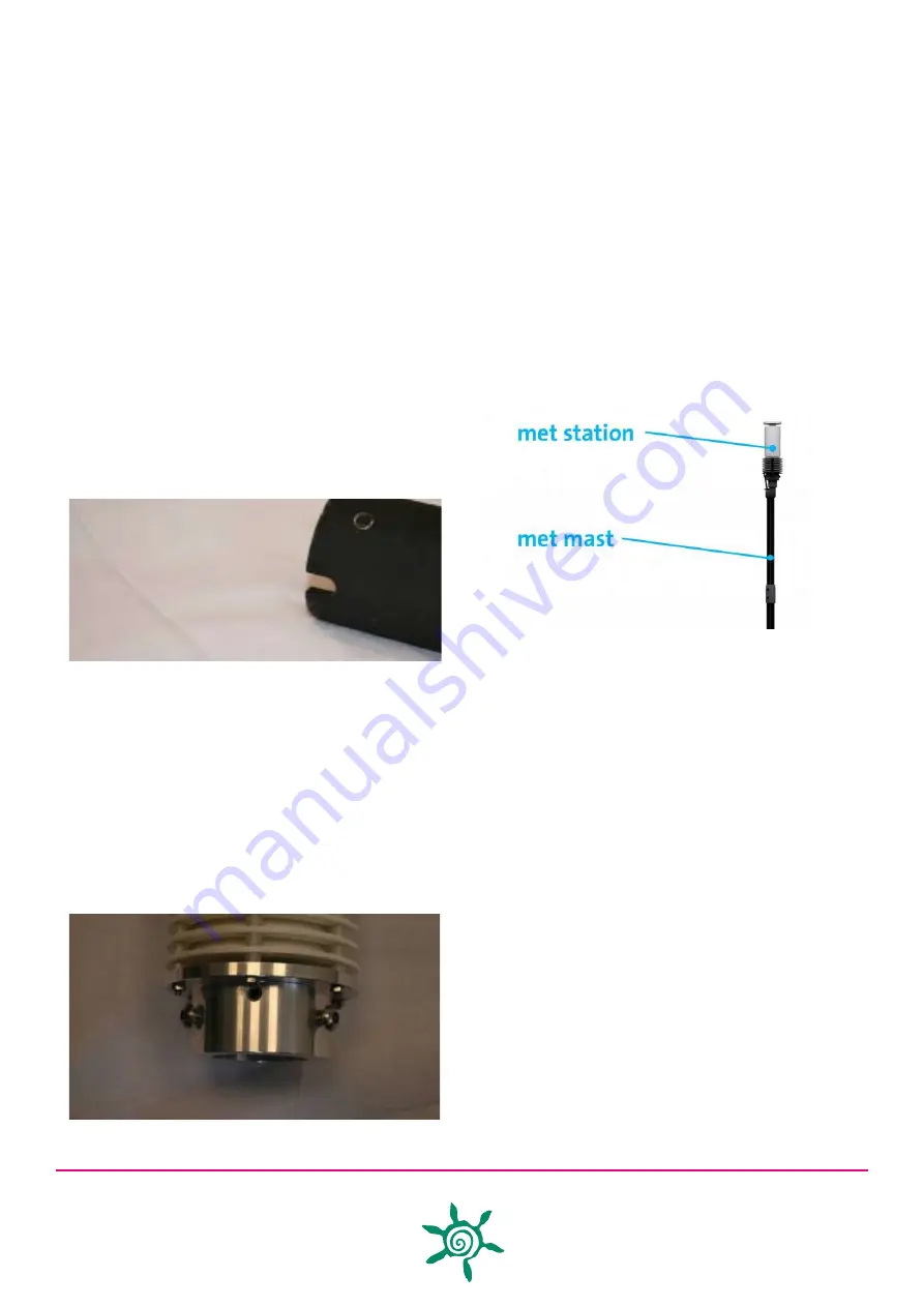
Alignment of the Met Station
Prior to alignment of the Met Station, the cable assembly
(QP0000-649) should be connected to the met station and
tightened.
On completion of the Met Mast alignment, the Met Station
is inserted onto the Mast Head, feeding the Met Station
cable assembly through the Mast Head.
The Met Station also includes an alignment key to ensure
that the assembly is not misaligned
Once located, the two ‘PinHead’ allen screws on the Met
Station assembly can be tightened.
3.
Met Mast Extension
Finally, the Met Mast can be extended to its full height,. This
is achieved by releasing the two ‘PinHead’ allen screws on
the upper mast clamp and extending the mast to full height
prior to re-tightening the allen screws.
4.
Met Mast Configuration complete
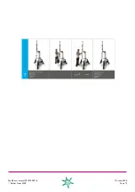
On completion of the Met Mast Configuration, the system
build should be complete as shown in the figure below;


