


ZephIR user manual QP1009-582 v2
© Natural Power 2008
10
th
June 2008
Page 21
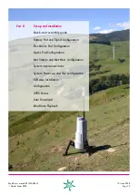
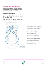
System Power-Up and
Site Configuration
On completion of the ZephIR configuration, the following
site configuration activities are required.
1.
System power-up
ZephIR is powered up using the button at the rear of the
system located on the top of the battery box.
Initiating a power-up sequence will turn on the system, and
all system functions will begin to operate.
On power-up, laser power will switch on automatically
unless disabled in the configuration.
Note: In extreme low temperatures, the system may require
a period of up to sixty minutes to reach a minimum
temperature for safe operation, whilst in extreme high
temperature the system may require a period of up to
ninety minutes to reach a maximum temperature for safe
operation.
2.
Customer interface enclosure
To enable system configuration, the customer interface
panel on the front of the system should be removed using
the four ‘PinHead’ allen screws.
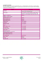
3.
System indicators
On completion of the power-up sequence, the system
indicators within the access panel should be in the following
status;
SYSTEM INDICATOR
STATUS
A5 - SUPPLY
ON
A12 - SUPPLY
ON
B - SUPPLY
ON
C - SUPPLY
ON
D - SUPPLY
ON
STATUS
FLASHING
COMMAND
OFF
TEMPERATURE
OFF
SERVICE S/W
OFF
SERVICE H/W
OFF
In the event that the system indicators are not as indicated
above, please refer to the troubleshooting guide at the rear
of the ZephIR system operations manual.
4.
SIM Card Insertion
In the interests of data security, the ZephIR system requires
the insertion of a user supplied SIM card. The modem is
located within the customer interface enclosure, behind a
secondary panel, which must be removed to gain access to
the SIM card.
This panel is removed by releasing the four ‘PinHead’ allen
screws located on the four corners of the panel. Note that
the SIM should be inserted with the system powered off.
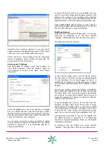
5.
GSM Communications
Following insertion of the SIM card, the user should ensure
that GSM communications to the system can be achieved by
dialling up the system using the ZephIR dial-up application
provided with the system.
Note: refer to the software systems overview for instructions
on setting up a new dial-up telephone number.
In the event that GSM communications are not achieved,
please refer to the troubleshooting guide at the rear of this
manual.
On successful completion of this test, the secondary panel
within the customer interface enclosure can be re-seated
and the ‘PinHead’ allen screws removed previously can be
re-tightened.
6.
Laptop connection
Connection of the laptop to the ZephIR system can either
be over the GSM communications or locally through the
ethernet connection. Connection should be initiated
through the ZephIR PC application provided with the
system. Once connected to the ZephIR system, the drop
down menus should be used to undertake the following
key steps. Note that a correct login will be required to
perform these actions.
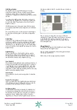
7.
Height Configuration
ZephIR is capable of indexing through five configurable
height settings (1m steps) for the purpose of data acquisition.
The minimum height available for data acquisition is 11m,
whilst the maximum height available for data acquisition is
200m. Please see the ZephIR configuration section for more
information.