5
6
Install - Under Sink
Naturally Filtered recommends you hire a licensed professional plumber for
installations under the sink. Working with plumbing without proper expertise can
lead to significant leaks and water damage to your home. These instructions are
a supplement and not a replacement for professional assistance.
Sample Install
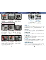
Step 1.
Shut off Cold Water
Turn cold water stop valve
clockwise to close. Turn
kitchen faucet to cold water to
verify water is off and relieve
pressure.
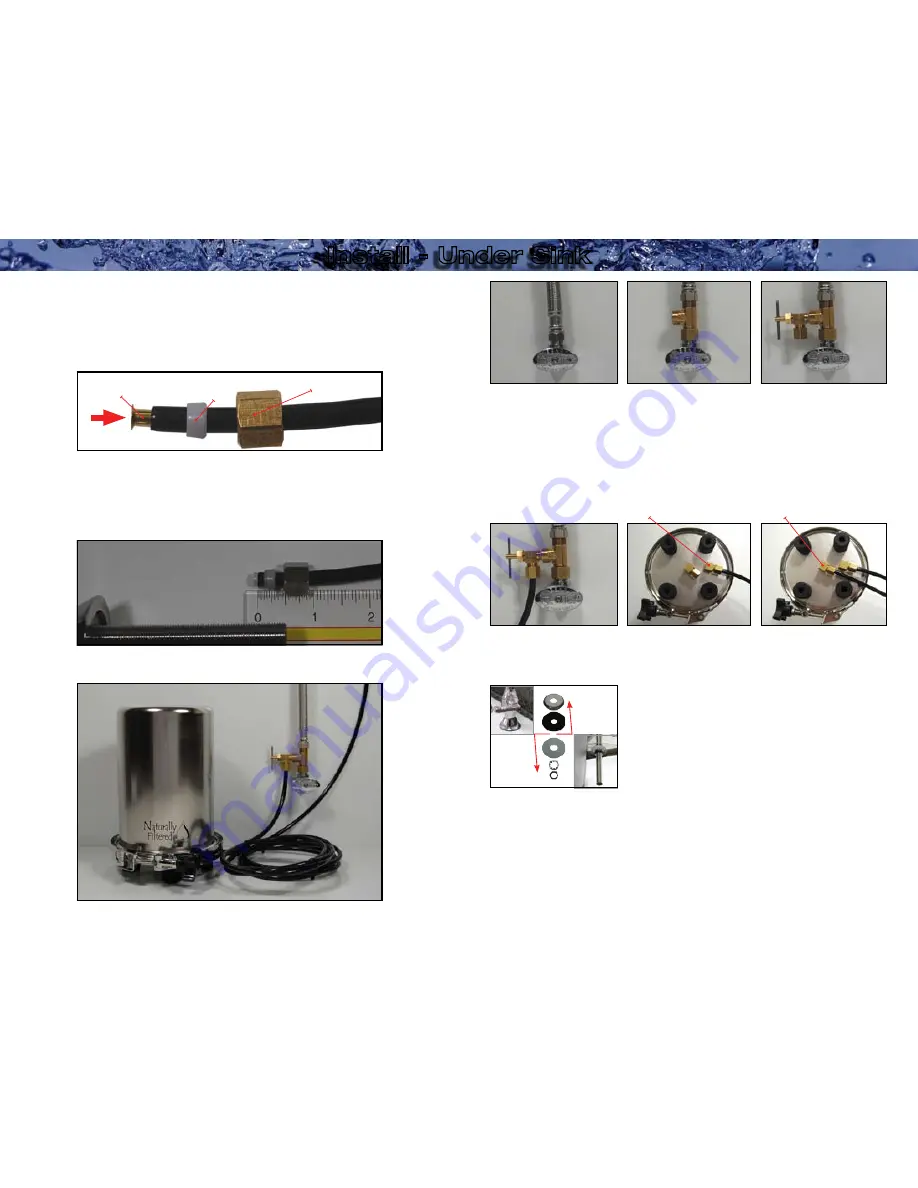
Step 3.
Shut-Off Valve
Thread Shut-Off Valve onto the
T of the T-Adaptor. Ensure the
Shut-Off Valve is accessible
for tubing installation.
In some
cases Shut-Off Valve may need
to be connected to T-Adaptor
prior to connecting to cold
water valve.
Step 2.
T-Adaptor
T-Adaptor should be
connected between the
cold water valve and the
plumbing line leading to the
main faucet.
Do not attempt
to disconnect tubing under
pressure.
Step 6.
Outlet Tubing
Connect tubing to Outlet
Fitting on Base
(See
Diagram A).
Step 5.
Inlet Tubing
Remove blue caps covering
inlet and outlet fittings.
Connect tubing to Inlet Fitting
on Base
(See Diagram A)
.
Step 4.
Shut-Off Valve Tubing
Connect tubing to Shut-Off
Valve
(See Diagram A).
Outlet
Inlet
Step 8.
Leak Check
Ensure Auxiliary Faucet and
Shut-Off Valve are closed.
Open cold water stop valve
slowly and check for leaks
on Shut-Off Valve and
T-Adaptor. If a leak is found,
close the cold water valve and
diagnose the leak. If there are
no leaks,
SLOWLY
open the
Shut-Off Valve and check the
system, Auxiliary Faucet, and
all tubing and fittings for leaks.
Step 9.
System Flush
Once you have verified that
the installation is free of leaks,
open the Auxiliary Faucet and
let water run for 3 - 5 minutes.
This will help eliminate air in
the line and flush carbon fines
from the cartridge. Close the
Auxiliary Faucet and do a final
leak check.
Your unit is now ready for
use.
Step 7.
Auxiliary Faucet
Install Auxiliary Faucet into pre-
cut hole on sink
.
Reference
Diagrams A and B for proper
tubing installation.
If tubing
is inserted too far into faucet
or compression nut is not
tightened tubing may blow off
during pressurization.
Pull on
tubing to test seal.
Below
Sink
Above
Sink
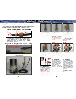
Diagram A - Compression Fitting Installation
Slip compression nut and plastic sleeve over tubing. Push brass
insert into tubing completely. Insert tubing into fitting. Connect
compression nut to fitting and thread down tightly to compress
plastic sleeve and create seal.
Brass
Insert
Plastic
Sleeve
Compression
Nut
Diagram B - Auxiliary Faucet Compression Fitting
Do not insert tubing more
than 1/2” into the faucet.


