12
13
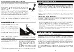
5. If you want to further increase the height of the tripod, you will need to use
the lock on the central column, which is visible in the lower left section of
Figure 6. Unscrew this lock anti-clockwise. Then pull out the head of the
tripod in order to raise the central column. Continue to pull it out until you
reach the desired height, then screw the lock closed. When the central co-
lumn is fully extended, you will have reached the maximum height possible,
which is 125 cm.
The optical tube of the portable telescope attaches to the tripod using the
turntable underneath the optical tube and the tripod mount platform. Above
all, check that all of the screws on the tripod are fully tightened.
1. Remove the protective paper covering the optical tube
2. Turn the upper right screw (see Figure 7) anticlockwise to unscrew it. This
will allow you to adjust the tripod platform by 90° as illustrated in Figure 8.
Once the platform has been adjusted, firmly tighten the screw.
3. Figure 9 shows the underside of the optical tube and the platform of the
tripod as well as the place where they attach together.
4. There is a screw fitted underneath the centre of the tripod platform (Figure 9)
which allows you to attach the platform to the optical tube of the telescope.
5. You can insert the screw into any of the threaded holes of the portable
telescope (whichever one you are using) on the mounting support of the optical
tube of the telescope. At this stage, the assembly should look like Figure 10.
6. To finish, unscrew the screw on the turntable and lower the turntable to the
right level, then firmly tighten the screw.
The portable telescope is easy to move in whichever direction you place it. Top to bottom rotation
(altitude) is controlled by the screw on the operating lever (Figure 1). The lateral rotation (azimuth)
is controlled by the azimuth screw handle (upper left handle in Figure 7). These two screw handles
can be unscrewed clockwise and tightened by screwing in the opposite direction. Unscrew these
handles to find objects easily (using the finderscope, detailed below), then re-tighten them.
(Figure 6)
(Figure 7)
(Figure 8)
(Figure 9)
(Figure 10)
ATTACHING THE OPTICAL TUBE OF THE PORTABLE TELESCOPE TO THE TRIPOD
MANUAL MOVEMENT OF THE PORTABLE TELESCOPE
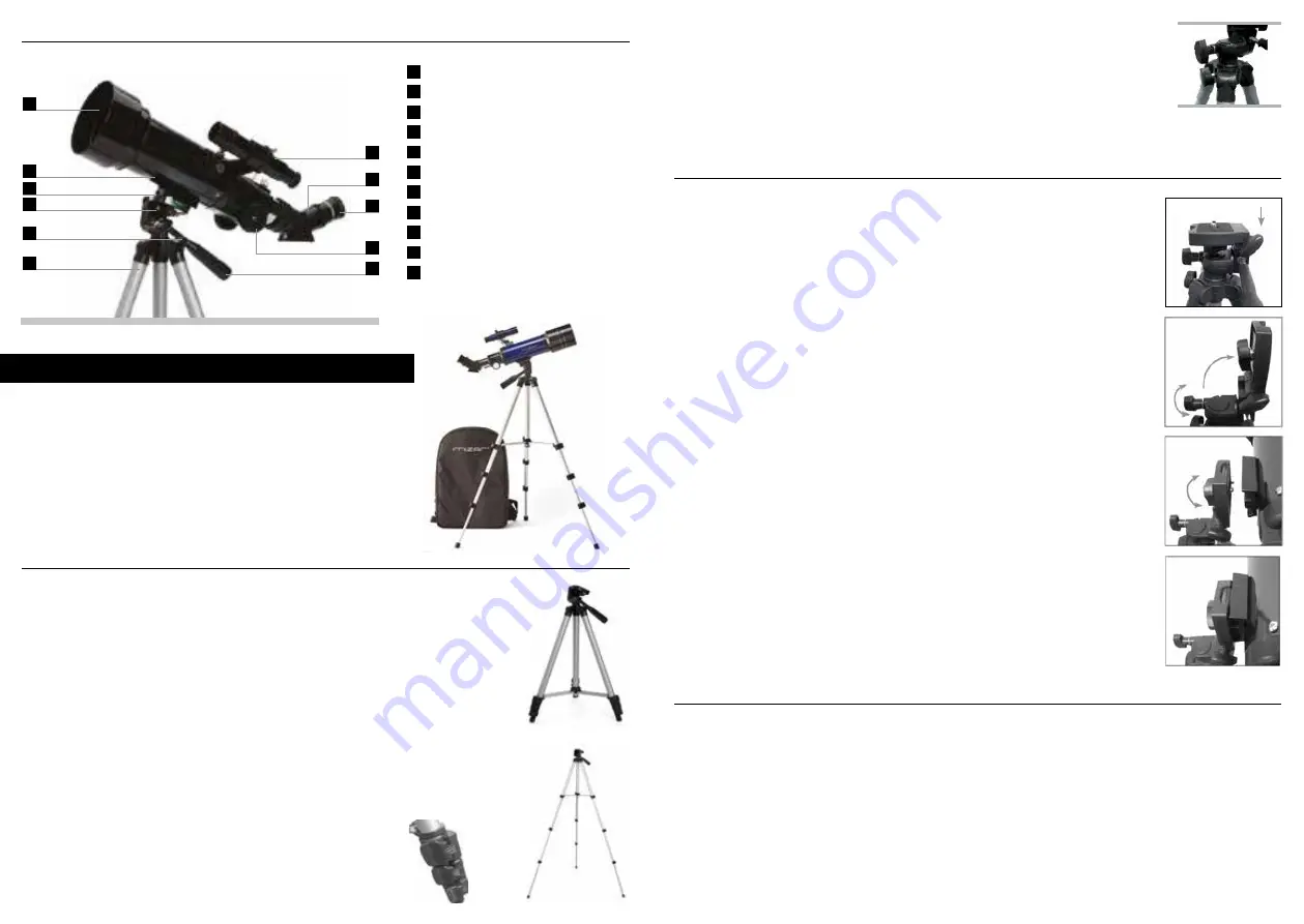
PARTS LIST
SETTING UP THE TRIPOD
ASSEMBLY
1
Eyepiece
2
Optical tube of the telescope
3
Platform on the head of the tripod
4
Azimuth lock
5
Central column lock
6
Tripod
7
Finderscope
8
Star diagonal image rectifier
9
Eyepiece
10
Collimation button
11
Operating lever
Altitude adjustment
This chapter explains how to assemble your portable te-
lescope.
The Mizar® portable telescope is delivered in a box. This
box contains the following parts: optical tube of the te-
lescope, tripod, star diagonal image rectifier, eyepiece 20
mm, eyepiece 10 mm, finderscope 5x24 with support. All
packaged in a backpack.
1. The tripod is pre-mounted in order to facilitate its use.
2. Stand up the tripod and fully extend the legs (Figure 3).
3. You can adjust the telescopic legs of the tripod to the desired height. The
lowest height is 41 cm and the highest is 125 cm.
4. To extend the length of the tripod, unscrew the locks at the base of each
leg on the tripod (Figure 4), opening the lock for each section extended.
Once unlocked, extend the leg of the tripod to its maximum length and
then screw the lock closed to set the leg in position. Repeat the process for
each leg on the tripod and each section until you achieve the desired height.
Figure 5 illustrates a fully extended tripod. Once all the sections of the legs
have been pulled out, the height will be around 107 cm.
1
2
3
4
5
6
7
8
9
10
11
(Figure 3)
(Figure 5)
(Figure 4)


