Page
8
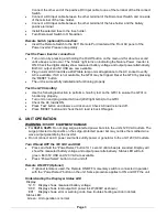
Connect the other end of the positive DC input cable to one of the terminal of the Disconnect
Switch.
Connect a DC input cable between the other terminal of the Disconnect Switch and one side
of the terminal of the fuse holder.
Connect a DC input cable between the other terminal of the fuse holder and the battery
positive terminal.
Install the selected fuse to the fuse holder.
Turn Disconnect Switch to ON position.
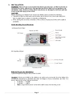
Remote Switch (optional) Connection:
Insert the Remote Switch to the RJ11 Remote Port located at the Front AC panel of the
Power inverter. Please note polarity.
Test the Power Inverter connection:
Turn unit on by pressing and holding the On/Off button on the main unit for about a second
until a beep sound occur
. The ‘Status’ light turns on indicating the Nature Power Inverter is
ON. Check the digital display show measured battery voltage and output power alternatively.
Both AC output and 5V USB are now available.
Plug in a small AC load like a 40W table lamp or small appliance to the AC socket to verify
AC is available. If AC is not available, the GFCI may be tripped. Reset the GFCI by pressing
the ‘RESET’ button.
The unit is successfully installed and functioning properly.
Test the GFCI monthly:
Use the following instruction to perform a monthly test on the GFCI to ensure the GFCI is
functioning properly.
Turn unit on and plug a small AC load (40W light bulbs) to the GFCI.
Check the AC load is ON.
Press ‘Test’ button and observe a click sound. Check AC load is turned off.
Press ‘RESET’ button and check the AC load is back ON again.
4. UNIT OPERATION
WARNING:
RISK OF EQUIPMENT DAMAGE
For
38210
,
38215
: Do not plug surge-
protected power bars into the unit’s 120 VAC outlets. The
surge protected components on the surge-protected power bar may not like the modified sine
wave output generate by the inverter.
Do not connect an AC power source like utility power or generator to the unit 120 VAC outlets.
Turn ON and OFF the 120 VAC and USB
Press and hold the
“Power/Select” button for 1 second until a beep is sounded. Display will
show the measured battery voltage and output power alternatively. Status LED will turn
green. Both 5V USB and 120 VAC are available.
Press
“Power/Select” button to turn unit off.
Remote ON /OFF (Optional)
If optional remote is used, the Remote ON/OFF momentary switch is connected in parallel
with the
“Power/Select” button on the unit. Same procedure applies to ON and OFF the unit.
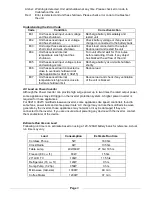
Understanding the Display & Status LED
Display:
’12.5’ Display shows measured battery voltage
‘0.80’ Display shows total output AC power in kW (800W as shown)
‘E01’
Display shows error or warning code. See trouble shooting section in details
Status LED:
Green: Unit operation is normal


