background image

Electronic pellet burner controller – NPBC-V3C-1/ NPBC-V4C-1/ NPBC-V4E-1

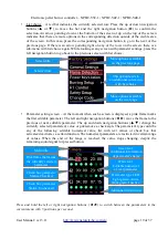
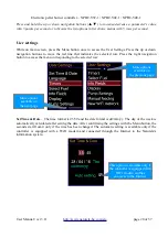
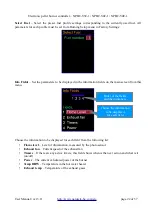
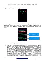
Common Factory Settings for all types of fuel:

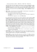
Equipment 

– Enable/disable the additional mechanisms and sensors of the burner's configuration and

set the polarity of the room thermostat's and the OD input's contacts:

General Settings

 – Set the internal auger motor's active time (Burner Feeder), the maximum allowed 

set temperature for the boiler, the main auger's capacity and pending time for FC output, if necessary. 

The internal auger motor always starts at the same time with the main auger and works for as long as it
is set in this menu. Its active time in seconds is:

T

ia

=

T

fa

Operation

100

+

Extra Sec

where: T

ia

 is the internal auger motor's active time;

T

fa

 is the fuel auger's active time (main auger).

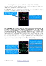
Instead of powerful cleaning fan, the FC output can control a mechanical cleaning actuator. During the
cleaning procedures where the FC output is active, the actuator moves in one direction to push out the
ashes. After the procedure is over the controller cuts the power supply to the FC output and the
actuator needs time to get back to its initial position. Put a check sign on the parameter FC output and

User Manual / ver 3.11


http://www.naturela-bg.com/en/


page 28 of 37

Put a check sign if the burner

works with an internal auger motor

Put check signs if the CH installation

has a room thermostat and its

contact is normally opened (NO)

Put a check sign if the burner

works with a high temperature

sensor for the exhaust gases

Put a check sign if the burner

works with an external stop switch

connected to the OD input

with normally closed contact (NC)

Check this box if the controller

comands a pump for

the hot water installation

The internal auger motor

will work 1.5 times longer

than the main auger

Additional seconds for

the internal auger's active time

If checked, every procedure where

FC output was supplied will be 

followed by the same amount of

time without any voltage to it

Set this parameter to assure the

accuracy of the statistical information

for pellet consumption.

Check the instructions how to

calibrate the auger motor on page 20.

Check this box if the controller

comands a pump for

the central heating installation

Summary of Contents for NPBC-V3C

Page 1: ... pellet burner controller NPBC V3C 1 NPBC V4C 1 NPBC V4E 1 Electronic Pellet Burner Controller NPBC V3C 1 NPBC V4C 1 NPBC V4E 1 SOFTWARE VERSION 56 27 User Manual ver 3 11 http www naturela bg com en page 1 of 37 ...

Page 2: ...in 10 minutes or less the burner will remain off because otherwise the extinguishing procedure may begin before the fire is stabilized If OD input activates during Ignition or Unfolding procedures the extinguishing procedure begins only after switching to any of the power levels 3 5 Software version 32 16 If the burner is on and timers are active holding the On Off button for more than 2 seconds d...

Page 3: ... functionality and a new improved executive module NPBC V4 or NPBC V4E This models most important advantages are Clearer and intuitive user interface with modern looking menus and 6 control buttons Additional warning messages about incorrect parameter input or if parameters from a different menu require corrections after the current changes The Control module can be equipped with a WiFi module NRM...

Page 4: ...rs runs up to two circulation pumps for the heating installation and for the hot water heater installation All of the controlled mechanisms must work on 220VAC or 110VAC mains power supply Important NPBC V4C controller must be powered at least 3 minutes for normal operation of the clock support system and burning process tracking when the power supply is switched off Hydraulic scheme of the outsid...

Page 5: ...thermostat for better control of the burning process according to the room temperature USB interface for connection with a computer NPBC V3C 1 NPBC V4C 1 INPUTS AND OUTPUTS DESCRIPTION Outputs Inputs FM Main fan RT Room thermostat To this input could be connected a normally opened or normally closed contact with no additional voltage FSG Fan for the flue gases PS Photo sensor SF Screw for fuel RB ...

Page 6: ...Electronic pellet burner controller NPBC V3C 1 NPBC V4C 1 NPBC V4E 1 User Manual ver 3 11 http www naturela bg com en page 6 of 37 ...

Page 7: ...Electronic pellet burner controller NPBC V3C 1 NPBC V4C 1 NPBC V4E 1 User Manual ver 3 11 http www naturela bg com en page 7 of 37 ...

Page 8: ...Electronic pellet burner controller NPBC V3C 1 NPBC V4C 1 NPBC V4E 1 User Manual ver 3 11 http www naturela bg com en page 8 of 37 ...

Page 9: ...er turns off and the burner goes to Unfolding fire phase to stabilize the fire If the pellets do not ignite during the set time for this the burner loads a new portion and makes a new attempt for ignition This happens only for the first 3 ignition retries and the pellet portion for each of them is respectively 100 50 and 25 of the set dose After the last attempt for ignition the burner stops and d...

Page 10: ...or detects that the fire is off the burner goes to cleaning phase and after that in initial state During the cleaning phase the main fan works on 100 of its power If there is an additional powerful cleaning fan or mechanical cleaning system connected to the FC output it turns on too The settings for cleaning before ignition after extinction and in case of a problem are different The procedure is a...

Page 11: ...hoto sensor The messages on the bottom line of the screen appear in different colors depending on the type of information they provide white text for the date green for the current work phase and red User Manual ver 3 11 http www naturela bg com en page 11 of 37 Time Boiler s water temperature External stop activated OD input Heating element ON Customized information fields Status bar with icons f...

Page 12: ... information Level of illumination measured by the photo sensor Exhaust fan s speed Information about the upcoming action of the timer If there are no active timers or the burner is in Standby mode there is no information under the icon If there is at least one activated timer and the burner is ON regardless of the fuel type the upcoming action On Off and the time for it or the day of the week if ...

Page 13: ... Clean 5 Suspend 10 Extinguishing While in Standby mode the burner doesn t work If it was working right before switching to this mode it will instantly start the extinguishing procedure It needs some time to completely put down the fire and to perform the Cleaning on Stop procedure The burner s and the boiler s aggregates might still work for some time during the Standby mode The installations cir...

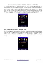
Page 14: ...e timers set the burner remains off and a warning message is displayed on the screen As soon as any of the timers is activated the burner will switch to Timers mode automatically How to change the set temperature for the boiler Press the up or down navigation buttons or while on main screen to enter the Set Temperature menu Press the up or down navigation buttons again to change the value in the r...

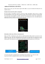
Page 15: ...corresponding date for the currently displayed information and below is the total consumption for this day Information about some of the current parameters While on Pellet consumption screen press the right navigation button again to access the next information screen It provides information about the boiler s set temperature the domestic hot water current temperature the level of illumination mea...

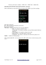
Page 16: ...m s current state can be any of the following Idle No connection with WiFi router Access point The modem is waiting for the local WiFi network s SSID and password APAssociated The modem is connected to a router Internet Access Established internet connection Connected The modem is connected to the information system s server Snd Rcv Sent Received data packages If the control module NRC 6 is not eq...

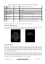
Page 17: ...y disappear after the reason for the message is no longer present Others can be dismissed by holding the left navigation button for more than 2 seconds while on main screen Table 2 Message Cleaning the error Description 1 Back burning Button The thermostat for back burning situation has been activated 2 Off boiler TS automatically Boiler s temperature sensor is disconnected 3 Short boiler TS autom...

Page 18: ...rrent menu caused changes in some of the parameters from a different menu the controller displays warning messages For example Parameter settings NPBC V3C 1 NPBC V4C 1 has two main groups of parameters with an option for a different access level to them User settings and Factory settings Press the Menu button once to enter the User settings They are available for any user at any time Press and hol...

Page 19: ...s or next editable parameter The up and down navigation buttons change the currently selected parameter s value or put remove a check sign The parameter s type could be any of the following editable numerical value list with text values or check box that activates deactivates a certain function The numerical parameters are restricted in certain range of values When the end of the range is reached ...

Page 20: ...responding to the selected row Set Time Date The time format is 23 59 and the date format is dd mm yy The day of the week is automatically calculated after setting the date After confirming the settings with the Menu button the seconds start from 0 only if the time has been changed The automatic setting is available only if the controller is equipped with a WiFi modem and connected through the Int...

Page 21: ... be active and there should not be any errors that require the burner to stay off The time in the column On must be before the time in the column Off If necessary set the Off time first to provide larger range for the On setting When using timers to control the burner it is more convenient to get information about their current state and their next action from one of the information fields on the ...

Page 22: ...information to be displayed for each field from the following list Flame level Level of illumination measured by the photo sensor Exhaust fan Current speed of the exhaust fan Timers If there are any active timers this field shows when is the next action and what is it on off Power The current calculated power of the burner Temp DHW Temperature in the hot water heater Exhaust temp Temperature of th...

Page 23: ...r in the boiler gets lower than the difference between Pump On and Hysteresis With the settings on the above screen the pump will turn off when the temperature of the water in the boiler gets lower than 60 5 55 When the room thermostat activates due to reaching its set temperature the pump keeps working but the burner s power decreases with one power level at a time until it gets to Suspend Set th...

Page 24: ...l heating installation works with a room thermostat and if it activates the CH pump stops If both installations don t need more heat the burner switches to Suspend power level If any of the installations needs heating the burner resumes its normal work and switches to the required power level according to the boiler s temperature When the time for Suspend power level is up the burner turns off if ...
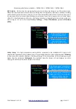
Page 25: ...onds are not enough repeat this step several times When the auger is full stop the manual feeding 3 Place a bucket or another tank at the end of the auger motor to collect the pellets 4 Start the manual feeding again and leave the auger working for any exact period see a list with the recommended periods for this setting in table 3 5 Remove the bucket and measure the weight of the collected pellet...

Page 26: ... menu helps with its initial setting or when changing the WiFi network Press the Menu button to exit this screen without making any changes Press the down navigation button to start the Access point mode The controller shows the following screen User Manual ver 3 11 http www naturela bg com en page 26 of 37 New WiFi network s name Confirmation for successful network installation ...

Page 27: ... its input Press the up or down navigation button to change the value for each position and the left right buttons to switch between positions Confirm the code with the Menu button Some of the parameters in the Factory settings are common for all types of fuel but others depend on the fuel type NPBC V3C supports settings for 4 different types of fuel Adjust the parameters for each fuel type by acc...

Page 28: ... over the controller cuts the power supply to the FC output and the actuator needs time to get back to its initial position Put a check sign on the parameter FC output and User Manual ver 3 11 http www naturela bg com en page 28 of 37 Put a check sign if the burner works with an internal auger motor Put check signs if the CH installation has a room thermostat and its contact is normally opened NO ...

Page 29: ... level the burner automatically switches to it If the difference doesn t increase the burner works on Suspend power level for as long as it is set in the parameter Duration min While on Suspend if the temperature of the boiler is still increasing when it gets higher than the set temperature with as many degrees as set in the parameter Overheating the burner will turn off immediately User Manual ve...

Page 30: ... Setup If a high temperature sensor pt100 is connected to the controller s PT input it will monitor the temperature of the exhaust gases If it gets higher than the value of the parameter Warning in this menu the controller displays a warning message If the temperature of the exhaust gases gets higher than the parameter Extinguish the controller turns the burner off and displays an alarm message In...

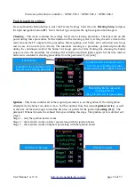
Page 31: ...ck the check box enter the code and then repeat it If you use less than 6 digits make sure to leave the same ones when you repeat the code If it is correctly set the next access to the Factory Settings will require access code Output test This menu directly controls all of the controller s outputs for test purposes only when the burner is in Standby mode Test the main and the exhaust fans speed by...

Page 32: ...gain Set the time interval between two automatic cleaning procedures from the parameter Cycle min Ignition This menu contains all of the required parameters to set the ignition If the first ignition attempt fails the burner can do few more Set their number from this menu Ignition retries as well as the time for the main auger to load the first dose of pellets for the ignition Loading Sec The param...

Page 33: ...settings for these power levels are identical Set the active time of the auger to load a portion of pellets Feed Sec and the cycle Cycle Sec between two portions The exact amount of the fuel as well as the speed of the main fan and the exhaust fan are important for the proper burning process It is recommended to set P3 for the maximum possible power that the burner can achieve P2 for 50 of P3 and ...

Page 34: ...use it periodically to clean the ashes Put a check sign on the line Activate to enable these procedures on the line Change fans to enable the usage of the fans during this procedure and or on the line FC Output to enable its usage Additional information about the controller After the power supply to the controller is on a yellow text with Control module s version appears on the screen for 2 second...

Page 35: ...Normally it should blink on 0 5 seconds If this is the case the problem might be in the connection between the modules If the LED is blinking on 2 4 seconds there is no software in the Executive module Use the remote monitoring and control program to upload the software in the module If the controller s version is in red there is a hardware incompatibility between the modules If the software versi...

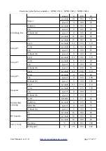
Page 36: ...y kg h 0 5 60 0 10 0 Flame Detection Ignition level 0 150 100 seconds 10 240 20 Extinction level 0 150 40 seconds 10 240 60 Power Modulation P3 ΔT C 2 30 10 P2 ΔT C 1 29 05 P1 ΔT C 0 28 00 Duration minutes 0 120 20 Overheating C 00 20 8 Cleaning Start Fan seconds 10 600 180 FC seconds 0 250 0 Stop Fan seconds 10 600 180 FC seconds 0 250 0 Alarm Fan seconds 10 600 180 FC seconds 0 250 0 Cycle minut...

Page 37: ... Cycle seconds 4 120 30 Fan speed 0 100 50 Exhaust fan speed 0 100 50 Setup Р3 Feed seconds 0 1 25 0 5 0 Cycle seconds 4 120 30 Fan speed 0 100 100 Exhaust fan speed 0 100 100 Suspend Feed seconds 0 1 25 0 2 0 Cycle seconds 4 120 120 Fan speed 0 100 5 Exhaust fan speed 0 100 5 Intermediate cleaning Cycle minutes 1 15 10 Duration seconds 4 120 30 Main fan speed 0 100 75 Exhaust fan speed 0 100 0 RT...

Reviews: