background image

Electronic pellet burner controller – NPBC-V3C-1/ NPBC-V4C-1/ NPBC-V4E-1

W

AY


OF

 O

PERATION


A  burner  controlled   by   NPBC-V3C-1/   NPBC-V4C-1   /   NPBC-V4E-1    can  work  in  continuous
automatic mode or in timer mode. While in timer mode, the burner works only during the intervals of
the day and the days of the week set by the user. While working, it goes through several stages:
cleaning,  igniting,  unfolding the fire, modulated  burning process according to the current and set
temperature of the boiler, intermediate cleaning performed during the burning process, extinguishing
and cleaning again. The current stage of the burner is displayed in green color on the bottom line of the
main screen.

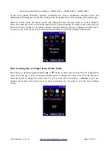
Every ignition begins with a cleaning cycle to clean all leftovers of the previous burning. At first only
the main fan works for as long as it is set in the menu 

Factory Settings → Burning Setup → Fuel X

→ Cleaning

, line 

Start

, column 

Fan

. Then the Cleaning fan also starts and works for as long as it is

set in the same menu, line  

Start

, column  

FC

. The cleaning procedure is followed by the  igniting

phase.

The  ignition procedure starts with loading the first fuel  dose in the burning chamber. The electrical
heater fires up the fuel while the fans provide the air flow. The procedure is performed in 3 stages.
During the first stage only the ignition heater works to reach the necessary temperature for ignition
faster. During the second and the third stages the ignition heater works along with the fans that provide
the necessary oxygen for the ignition and blow the heat from the heater to the fuel. It is recommended
to set lower speed for the fans during the second stage, so that they won't cool down and blow off the
flame and higher speed for the third stage to increase the air flow. To set the maximum duration of
each stage and the fans' speed go to the menu  

Factory Settings → Burning Setup → Fuel X →

Ignition

. When the photo sensor detects the light from the burning fire, the ignition heater turns off

and the burner goes to Unfolding fire phase to stabilize the fire. If the pellets do not ignite during the
set time for this, the burner loads a new portion and makes a new attempt for ignition. This happens
only for the first 3 ignition retries and the pellet portion for each of them is respectively 100%, 50%
and 25% of the set dose. After  the last attempt for ignition, the burner stops and displays an error
message for ignition fail. The parameters for the first dose and the ignition can be set in the menu as
many retries as set in the menu  

Factory Settings → Burning Setup → Fuel X → Ignition

. The

parameters  for detection  of the  burning fire  can be  set in the  menu  

Factory  Settings → Flame

Detection

The successful ignition is followed by the smooth unfolding procedures. If the burner goes instantly to
burning on 3

rd

 power level, when the fire is still unstable and the burning chamber is cold, the high air

flow from the fan might blow off or smother the flame. To avoid this, the burner waits for the first
dose of pellets to burn out and then slowly increases the power to the highest required power level
according to the temperature difference between the set temperature and the current temperature of the
boiler, starting with the lowest level P1. The parameters for the Unfolding fire process can be set from
the menu 

Factory Settings → Burning Setup → Fuel X → Unfolding Fire

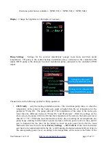
The next phase is the burning control. NPBC-V3C-1 has settings for 4 different power levels. Three of
them are used for the burner's normal work. The 4

th

 power level maintains the burning fire to avoid

unnecessary cycles of extinguishing, cleaning and ignition when the water in the boiler has reached the
set temperature. Of course, if there is no need for more heat in the heating installation for longer period
of time, the burner turns off. The portion of pellets for each power level is a function of the auger
motor's capacity and activate time and the cycle between two of its turnings on. The parameters for
each power level's settings are auger motor's active time, cycle between two turnings on and main and

User Manual / ver 3.11


http://www.naturela-bg.com/en/


page 9 of 37

Summary of Contents for NPBC-V4E-1

Page 1: ...pellet burner controller NPBC V3C 1 NPBC V4C 1 NPBC V4E 1 Electronic Pellet Burner Controller NPBC V3C 1 NPBC V4C 1 NPBC V4E 1 SOFTWARE VERSION 56 27 User Manual ver 3 11 http www naturela bg com en p...

Page 2: ...n 10 minutes or less the burner will remain off because otherwise the extinguishing procedure may begin before the fire is stabilized If OD input activates during Ignition or Unfolding procedures the...

Page 3: ...unctionality and a new improved executive module NPBC V4 or NPBC V4E This models most important advantages are Clearer and intuitive user interface with modern looking menus and 6 control buttons Addi...

Page 4: ...s runs up to two circulation pumps for the heating installation and for the hot water heater installation All of the controlled mechanisms must work on 220VAC or 110VAC mains power supply Important NP...

Page 5: ...hermostat for better control of the burning process according to the room temperature USB interface for connection with a computer NPBC V3C 1 NPBC V4C 1 INPUTS AND OUTPUTS DESCRIPTION Outputs Inputs F...

Page 6: ...Electronic pellet burner controller NPBC V3C 1 NPBC V4C 1 NPBC V4E 1 User Manual ver 3 11 http www naturela bg com en page 6 of 37...

Page 7: ...Electronic pellet burner controller NPBC V3C 1 NPBC V4C 1 NPBC V4E 1 User Manual ver 3 11 http www naturela bg com en page 7 of 37...

Page 8: ...Electronic pellet burner controller NPBC V3C 1 NPBC V4C 1 NPBC V4E 1 User Manual ver 3 11 http www naturela bg com en page 8 of 37...

Page 9: ...r turns off and the burner goes to Unfolding fire phase to stabilize the fire If the pellets do not ignite during the set time for this the burner loads a new portion and makes a new attempt for ignit...

Page 10: ...r detects that the fire is off the burner goes to cleaning phase and after that in initial state During the cleaning phase the main fan works on 100 of its power If there is an additional powerful cle...

Page 11: ...oto sensor The messages on the bottom line of the screen appear in different colors depending on the type of information they provide white text for the date green for the current work phase and red U...

Page 12: ...information Level of illumination measured by the photo sensor Exhaust fan s speed Information about the upcoming action of the timer If there are no active timers or the burner is in Standby mode the...

Page 13: ...Clean 5 Suspend 10 Extinguishing While in Standby mode the burner doesn t work If it was working right before switching to this mode it will instantly start the extinguishing procedure It needs some t...

Page 14: ...timers set the burner remains off and a warning message is displayed on the screen As soon as any of the timers is activated the burner will switch to Timers mode automatically How to change the set...

Page 15: ...orresponding date for the currently displayed information and below is the total consumption for this day Information about some of the current parameters While on Pellet consumption screen press the...

Page 16: ...s current state can be any of the following Idle No connection with WiFi router Access point The modem is waiting for the local WiFi network s SSID and password APAssociated The modem is connected to...

Page 17: ...disappear after the reason for the message is no longer present Others can be dismissed by holding the left navigation button for more than 2 seconds while on main screen Table 2 Message Cleaning the...

Page 18: ...rent menu caused changes in some of the parameters from a different menu the controller displays warning messages For example Parameter settings NPBC V3C 1 NPBC V4C 1 has two main groups of parameters...

Page 19: ...or next editable parameter The up and down navigation buttons change the currently selected parameter s value or put remove a check sign The parameter s type could be any of the following editable nu...

Page 20: ...esponding to the selected row Set Time Date The time format is 23 59 and the date format is dd mm yy The day of the week is automatically calculated after setting the date After confirming the setting...

Page 21: ...be active and there should not be any errors that require the burner to stay off The time in the column On must be before the time in the column Off If necessary set the Off time first to provide larg...

Page 22: ...nformation to be displayed for each field from the following list Flame level Level of illumination measured by the photo sensor Exhaust fan Current speed of the exhaust fan Timers If there are any ac...

Page 23: ...in the boiler gets lower than the difference between Pump On and Hysteresis With the settings on the above screen the pump will turn off when the temperature of the water in the boiler gets lower tha...

Page 24: ...heating installation works with a room thermostat and if it activates the CH pump stops If both installations don t need more heat the burner switches to Suspend power level If any of the installatio...

Page 25: ...nds are not enough repeat this step several times When the auger is full stop the manual feeding 3 Place a bucket or another tank at the end of the auger motor to collect the pellets 4 Start the manua...

Page 26: ...menu helps with its initial setting or when changing the WiFi network Press the Menu button to exit this screen without making any changes Press the down navigation button to start the Access point mo...

Page 27: ...its input Press the up or down navigation button to change the value for each position and the left right buttons to switch between positions Confirm the code with the Menu button Some of the paramete...

Page 28: ...over the controller cuts the power supply to the FC output and the actuator needs time to get back to its initial position Put a check sign on the parameter FC output and User Manual ver 3 11 http www...

Page 29: ...level the burner automatically switches to it If the difference doesn t increase the burner works on Suspend power level for as long as it is set in the parameter Duration min While on Suspend if the...

Page 30: ...Setup If a high temperature sensor pt100 is connected to the controller s PT input it will monitor the temperature of the exhaust gases If it gets higher than the value of the parameter Warning in thi...

Page 31: ...k the check box enter the code and then repeat it If you use less than 6 digits make sure to leave the same ones when you repeat the code If it is correctly set the next access to the Factory Settings...

Page 32: ...ain Set the time interval between two automatic cleaning procedures from the parameter Cycle min Ignition This menu contains all of the required parameters to set the ignition If the first ignition at...

Page 33: ...ettings for these power levels are identical Set the active time of the auger to load a portion of pellets Feed Sec and the cycle Cycle Sec between two portions The exact amount of the fuel as well as...

Page 34: ...se it periodically to clean the ashes Put a check sign on the line Activate to enable these procedures on the line Change fans to enable the usage of the fans during this procedure and or on the line...

Page 35: ...ormally it should blink on 0 5 seconds If this is the case the problem might be in the connection between the modules If the LED is blinking on 2 4 seconds there is no software in the Executive module...

Page 36: ...ty kg h 0 5 60 0 10 0 Flame Detection Ignition level 0 150 100 seconds 10 240 20 Extinction level 0 150 40 seconds 10 240 60 Power Modulation P3 T C 2 30 10 P2 T C 1 29 05 P1 T C 0 28 00 Duration minu...

Page 37: ...Cycle seconds 4 120 30 Fan speed 0 100 50 Exhaust fan speed 0 100 50 Setup 3 Feed seconds 0 1 25 0 5 0 Cycle seconds 4 120 30 Fan speed 0 100 100 Exhaust fan speed 0 100 100 Suspend Feed seconds 0 1 2...

Reviews: