Cabling Instructions
July 6, 2020
4-3
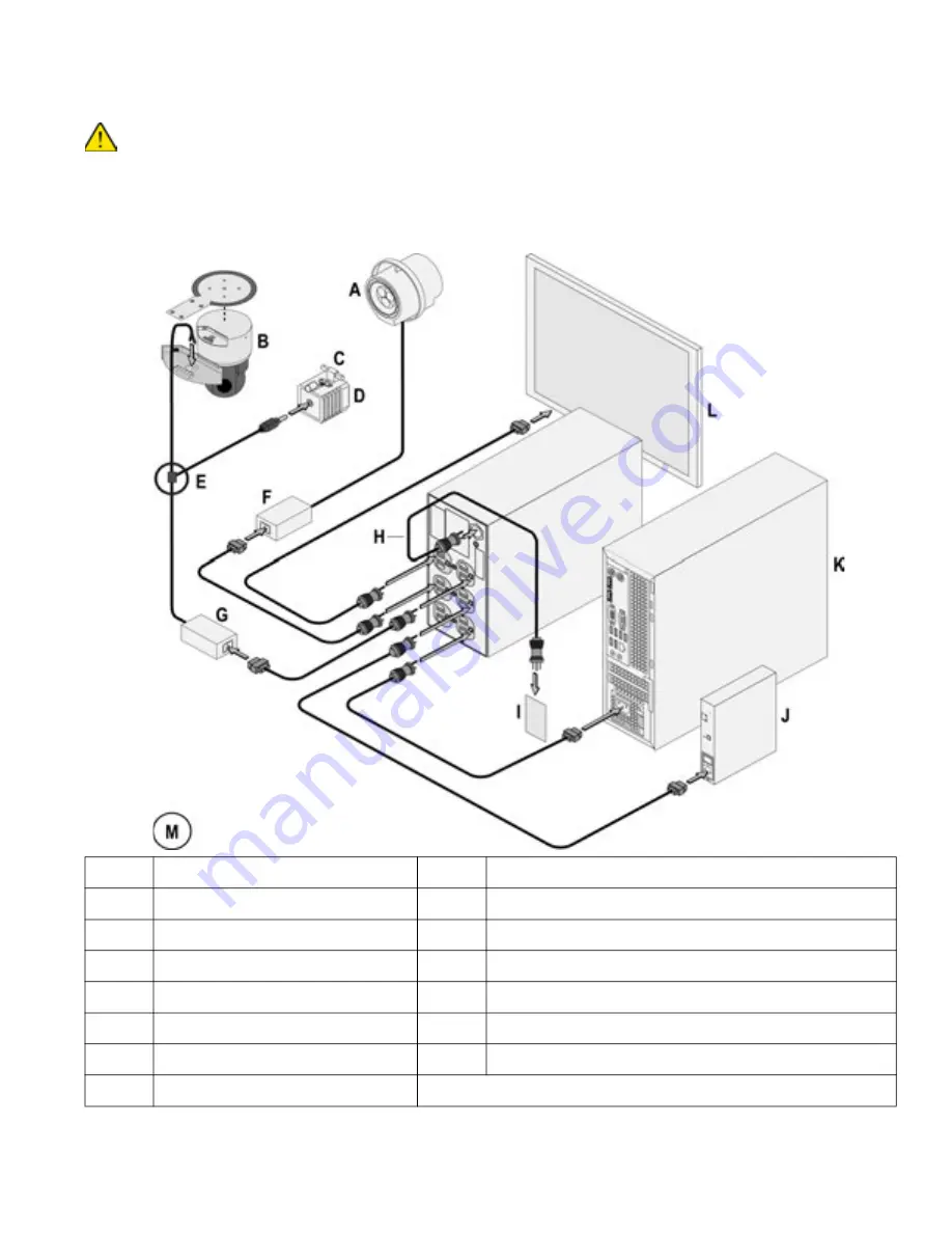
System power cables connections -
Natus ErgoJust LTM
Ensure that the ISO or UPS is disconnected (unplugged) from the MAINS power source before connecting power cables to
the system components.
NOTE:
ISO is shown in the example below.
See the cable routing diagram on the next page.
Figure 1: Cabling the system components power.
Legend Description
Legend Description
A
Natus Photic Stimulator (option)
H
ISO or UPS
B
Video camera
I
MAINS
C
Microphone
J
Natus Amplifier Base Unit (right side)
D
IR Light
K
Computer
E
Cable splitter
L
Monitor
F
Power supply
M
Connectors and device styles may vary from those shown.
G
Power supply


