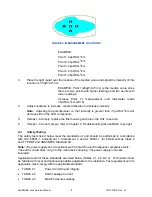
FIGURE 3 - MEASUREMENT LOCATIONS
EXAMPLE:
Point 1: 29µW/cm
2
/nm
Point 2: 33µW/cm
2
/nm
Point 3: 32µW/cm
2
/nm
Point 4: 27µW/cm
2
/nm
Point 5: 25µW/cm
2
/nm
3.
Place the light meter over the location of the median value and adjust the intensity of this
location to 35 µW/cm
2
/nm.
EXAMPLE: Point 1(29µW/cm
2
/nm) is the median value since
there are two points with higher readings and two points with
lower readings.
Increase Point 1’s measurement until radiometer reads
35µW/cm
2
/nm (29+6).
4.
Adjust clockwise to increase, counterclockwise to decrease intensity.
Note: Adjusting the potentiometer so that intensity is greater than 35 µW/cm
2
/nm will
decrease life of the LED components.
5.
If steps 1-4 comply, replace the filter housing and return the UUT to service.
6.
If steps 1-4 do not comply, refer to Chapter 3, Troubleshooting the neoBLUE cozy light.
2.3 Safety
Testing
The safety tests listed below meet the standards of, and should be performed in accordance
with, IEC 60601-1, Amendment 1, Amendment 2, and UL 60601-1, for instruments as Class 2
and TYPE BF and ANSI/NFPA Standard 99.
Note: The power supply has a functional earth contact for electromagnetic compliance tests.
The earth contact does not go to the main device housing. The power supply is double
insulated.
Applicable tests for these standards are listed below (Tables 2.1, 2.2 & 2.3). Technicians must
be familiar with local and national standards applicable to the institution. Test equipment and its
application must comply with the applicable standard.
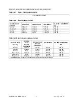
TABLE 2.1
Power Cord Ground Integrity
TABLE 2.2
Earth Leakage Current
TABLE 2.3
Main Enclosure Leakage
neoBLUE® cozy Service Manual
8
P/N 051915 Rev.
D

