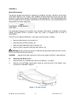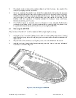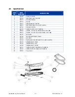
CAUTION: Do not grasp the LED components to remove the LED PCB from the light enclosure.
Pull up from the edges of the PCB, starting from the end under the fan.
4.
If you are replacing the LED PCB, obtain the replacement and place into enclosure.
5.
Reconnect connectors to JP1, JP2, JP3, and JP4 and secure the ferrite with a new cable
tie.
Note:
When reconnecting the LED PCB, verify the JP1, JP2, JP3, and JP4 connectors
are mated correctly.
6.
If no further repair is required, reverse all previous steps in Chapter 4, return to Chapter
2, and complete Performance Verification and Safety Tests.
4.3
Removing the ON/Standby Switch
The procedure in Section 4.1 must be completed before beginning these steps.
1.
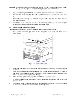
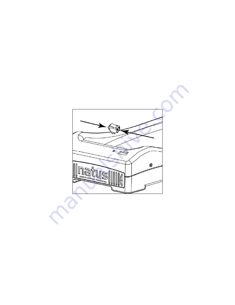
The switch is held in the light enclosure by spring tabs, two on each side of the switch.
See Figure 7.
Figure 7 – Switch Removal
2.
Press the tabs against the switch body while pushing the switch out the top of the light
enclosure.
Note: During reinstallation, orient the switch so that the outermost terminal is closest to
the center of the device as shown in Figure 7. When installed correctly, the device will
turn on when the switch is pressed to the right.
3.
Disconnect the quick-connect spade terminals from the power switch.
If you are replacing the ON/Standby switch, obtain the replacement and reverse the
previous steps.
4.
If no further repair is required, reverse all previous steps in Chapter 4, return to Chapter
2, and complete Performance Verification and Safety Tests.
neoBLUE® cozy Service Manual
17
P/N 051915 Rev.
D

