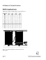
Stage 1 of Tuning Procedure
Initial Setting of L Tuning Taps (
LOCAL
control,
TUNE SETUP
on)
Page 2-12
ATU-HP Technical Instruction Manual
Issue 2.0
Section 2 Preparation for Use and Installation
Paragraph 2.5 continued
(d) Gain access to the ATU-HP’s control
circuitry, by removing the transparent
cover across the front of the cabinet,
noting it is secured by four screws, two
on either side of the cabinet.
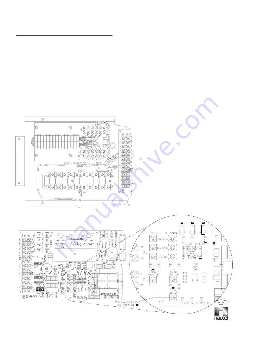
(e) Configure the RF wiring at the ATU
control/monitor PWB’s terminal block
(A1TB1) and the matching transformer
terminal blocks (T1-TB1 and T1-TB2)
as shown in Figure 2-4. Disconnect
wiring from capacitor bank as
necessary.
(f) Turn on the ATU-HP’s ac power
supply. On ATU control/monitor PWB
A1, press the
LOCAL/REMOTE
(S4)
and
TUNE SETUP
(S9) so that the
LOCAL
and
TUNE SETUP
LEDs turn
on. See Figure 2-5.
Figure 2-4 - Initial RF Wiring Connections
Figure 2-5 - ATU Control/Monitor PWB – Pushbutton Switches and LEDs
A1TB1
T1


