Stage 2 of Tuning Procedure
Determining Antenna Resistance (
LOCAL
control,
TUNE SETUP
on)
Page 2-14
ATU-HP Technical Instruction Manual
Issue 2.0
Section 1 Preparation for Use and Installation
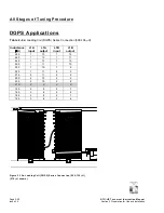
Figure 2-7 – Post-Inductive Tuning RF Wiring Connections
Paragraph 2.5 continued
(i)
Turn transmitter off. Configure the RF
wiring between the ATU control/
monitor PWB’s terminal block
(A1TB1) and the matching
transformer terminal blocks (T1-TB1
and T1-TB2) as shown in Figure 2-7,
noting the blue wire should be
terminated on T1-3 and the red wires
should be terminated on A1TB1-5 and
A1TB1-6.
(j) Using the flow diagram illustrated in
Figure 2-8, determine the antenna
resistance by selecting the T1 tap
settings that provide minimum reflected
power. View reflected power on the
ATU control/monitor PWB’s meter,
noting switch A1S10 must be set to
REFLD PWR
and switch A1S11 must
be set to
RF POWER
.
NOTE
Forward power must be maintained at the
same level when determining the reflected
power. After each tapping of T1, allow the
loading coils to retune (i.e.,
L TUNING
-
NORMAL LED turned on).
(k) When step (j) is complete, use Table
2-3 to determine the antenna system
resistance associated with the T1
connections that provided minimum
reflected power.
A1TB1
T1


