ATU-HP Technical Instruction Manual
Page 3-5
Section 3 Operating Instructions
Issue 2.0
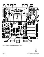
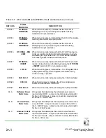
Table 3-1: ATU Control/Monitor PWB Controls and Indicators
(Continued)
REF
DES
PANEL
MARKING
DESCRIPTION
A1F1
A1F2
Ac Input Fuses
Fuse the ac power source voltage applied to A1TB2-1 (A1F2)
and A1TB2-3 (A1F1) at 0.25 A.
A1M1
Meter
Analog meter that displays the following ATU-HP parameters:
Forward power, on one of two scales (0 - 4000 W or 0 -
1200 W), when switch A1S10 is set to
FWD PWR
and switch
A1S11 is set to
RF POWER
.
Reflected power, on one of two scales (0 – 400 W or 0 -
120 W), when switch A1S10 is set to
REFLD PWR
and
switch A1S11 is set to
RF POWER
.
Antenna current, on one of two scales (0 – 30 A or 0 – 10 A),
when switch A1S11 is set to
RF CURRENT
.
The modulation 0 – 100% scale is not used in the ATU-HP.
A1R51
ANT CUR
SAMPLE
Factory adjusted to provide an antenna current sample,
monitored by the associated transmitter via a serial link, of
4 V when the antenna current is 30 A.
A1R70
METER CAL
Factory adjusted to set the series resistance of meter A1M1
to a precise value for meter accuracy.
A1S1
L TUNING –
INCREASE
When pressed (in local mode only), causes a manual
increase in the ATU-HP’s loading coil inductance. If the
ATU-HP was tuned, the
L TUNING – DECREASE
LED will
turn on, indicating the ATU-HP is no longer tuned. The ATU-
HP will restore a tuned condition, if auto tuning is not
inhibited.
A1S2
L TUNING –
DECREASE
When pressed (in local mode only), causes a manual
decrease in the ATU-HP’s loading coil inductance. If the
ATU-HP was tuned, the
L TUNING – INCREASE
LED will
turn on, indicating the ATU-HP is no longer tuned. The ATU-
HP will restore a tuned condition, if auto tuning is not
inhibited.
A1S3
L TUNING –
INHIBIT
When pressed (in local mode only), disables the ATU-HP’s
automatic inductance tuning function. Associated
L TUNING
– INHIBIT
LED will turn on.


