WARNING
Extremely high, potentially lethal, RF voltages are present in the ATU-HP when an RF
input is being applied. Use extreme caution during maintenance or troubleshooting
inside the ATU-HP cabinet. Where possible, turn off the associated transmitter.
ATU-HP Technical Instruction Manual
Page 4-1
Section 4 Testing and Adjustment
Issue 2.0
ATU-HP
TECHNICAL INSTRUCTION MANUAL
Section 4
TESTING AND ADJUSTMENT
4.1 INTRODUCTION
This section contains step-by-step
calibration procedures for the antenna
tuning unit (ATU) using precision test
equipment and a functional test procedure
using integral meters.
NOTE
It is recommended that personnel who are
not familiar with detailed circuit theory or do
not realize the impact a specific adjustment
will have on other steps, follow the
instructions in the order they are
presented. These adjustments should be
performed during initial turn-on and after
major repairs or a frequency change.
4.2 OPERATING PRECAUTIONS
Operation of the ATU-HP is fully automatic
except when the manual override switches
are activated. Maintainers should read and
fully understand the
Operating Instructions
section, particularly the controls and
indicators section.
4.3
FUNCTIONAL TESTS
Successful completion of the following
tests will verify the ATU-HP circuits are
within factory specifications.
4.3.1 General
The functional tests should be performed
and the results recorded for comparison
with past and future test results, as a
routine part of scheduled maintenance
checks and as the first step in
troubleshooting procedures.
4.3.1.1
The functional test procedures are
provided in a step-by-step format. This
method of presentation will permit a person
who is unfamiliar with the transmitter to
perform the functional tests in a logical
sequence. It is recommended the
procedures be completed in sequence, as
each procedure establishes switch settings
and contains prerequisites for subsequent
procedures.
4.3.2 Initial Settings
Set the controls as follows prior to initial
turn-on:
(a) Verify transmitter RF output is turned
off.
(b) Gain access to the interior of the ATU
cabinet by disengaging the front
cover’s pull-down latches. Carefully
remove front cover.
WARNING
Connect grounding clip (located near
the RF input) to the RF input.
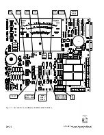
(c) Press
LOCAL/REMOTE
switch A1S4.
LOCAL
LED A1DS1 will turn
ON
.
(d)
Press
INHIBIT L TUNING
switch
A1S3.
INHB L TUNING
LED A1DS10
will turn
ON
.
(e) Press
INHIBIT R TUNING
switch
A1S7.
INHB R TUNING
LED A1DS17
will turn
ON
.


