GV60 TROUBLESHOOTING MANUAL
RESPONDING TO ALARMS
VERSION 1.0 2018-01-01
PAGE 4.1.19
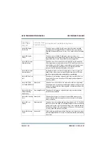
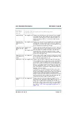
Controller: SWR
Shutback
Output Network (red) This alarm occurs if the transmitter's reflected power exceeds the SWR
shutback threshold (7200 W). The transmitter will shut back and attempt to
find a safe operating point by entering its SWR foldback mode. This may be
the result of a transient SWR condition (arc or lightning) within the output
transmission line or antenna system. Attempt to reset the latched condition
by pressing Reset [using the AUI’s Reset button (see
of the Operations and Maintenance Manual) or using
the controller UI (see
“Resetting Alarms - Using the Controller UI”
of the Operations and Maintenance Manual)]. Inspect
the output transmission line and antenna for punctures or damage. If no
damage can be found, suspect the output power probe (A15). See also
Cutback Active alarm.
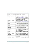
Controller:
Transmitter PA
Biasing
-
This is an informational alarm only that is displayed when the bias routine
has been initiated.
Controller: Turn On
Delay (Delaying Turn
On)
Exciter (red)
This alarm occurs, if the turn-on delay function is enabled, and transmitter is
not permitted turn-on until the delay period elapses. The turn-on delay
function is enabled upon an ac power failure and is typically used to add
delay for use with an external generator.
Controller: Very Low
Forward Power (Very
Low Fwd Power)
Output Network
(amber)
This alarm occurs if transmitter’s average forward power is below the low
forward power threshold (defaulted to 12.5% of the setpoint and is user
adjustable). Check for associated alarms, and follow the associated
troubleshooting procedure, if present.
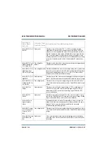
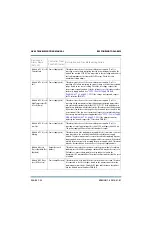
Controller: +1.2V Fail Power Supply (red)
This alarm occurs if the +1.2 V supply in the controller is 10% higher or
10% lower than its desired value. Check the output voltage of the LVPS
module. If necessary, replace the LVPS (see
Module Replacement” on page 4.1.50
). There may also be a problem
with the controller’s power supply PWB.
Controller: +1.8V Fail Power Supply (red)
This alarm occurs if the +1.8 V supply in the controller is 10% higher or
10% lower than its desired value. Check the output voltage of the LVPS
module. If necessary, replace the LVPS (see
Module Replacement” on page 4.1.50
). There may also be a problem
with the controller’s power supply PWB.
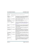
Controller: +3.3V Fail Power Supply (red)
This alarm occurs if the +3.3 V supply in the controller is 10% higher or
10% lower than its desired value. Check the output voltage of the LVPS
module. If necessary, replace the LVPS (see
Module Replacement” on page 4.1.50
). There may also be a problem
with the controller’s power supply PWB.
Device and
Alarm Name
(AUI, UI)
Controller Front
Panel LED (color)
Description and Troubleshooting Action
Summary of Contents for GV60
Page 2: ......
Page 4: ......
Page 8: ...GV60 TROUBLESHOOTING MANUAL PAGE 4 VIII VERSION 1 0 2018 01 01 ...
Page 102: ...GV60 TROUBLESHOOTING MANUAL PARTS LISTS PAGE 4 2 12 VERSION 1 0 2018 01 01 ...
Page 463: ...VERSION 1 0 2018 01 01 MD 17 Figure MD 17 NAPA31C Power Amplifier PWB Q1 ...
Page 475: ...GV60 TROUBLESHOOTING MANUAL LIST OF TERMS PAGE 4 6 2 VERSION 1 0 2018 01 01 ...
Page 476: ......


