GV60 TROUBLESHOOTING MANUAL
RESPONDING TO ALARMS
PAGE 4.1.30
VERSION 1.0 2018-01-01
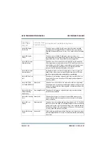
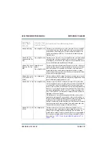
Rack #: LVPS 1/2 A (or
B) Fail
Power Supply (red)
This alarm occurs if LVPS module 1A (U2), 1B (U3), 2A (U102), or 2B (U103)
is reporting a PS failure, indicating its output voltage is outside its
acceptable range, based on the control setting. Check the dc output voltage
of the suspect LVPS. If the dc voltage is out of tolerance, replace the LVPS
module (see
“LVPS / Power Supply Module Replacement” on
). If the dc voltage is acceptable, suspect the PS interface
PWB (A1).
Rack #: LVPS 1/2 A (or
B) AC Fail
Power Supply (red)
This alarm occurs if LVPS module 1A (U2), 1B (U3), 2A (U102), or 2B (U103)
is reporting an ac failure, indicating its ac input voltage is less than 175 V
ac. Check the ac voltage applied to the suspect LVPS module. If the ac
voltage is acceptable, replace the LVPS module (see
Supply Module Replacement” on page 4.1.50
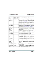
Rack #: LVPS 1/2 A (or
B) High Temperature
[LVPS A (or B) Temp]
Power Supply (red)
This alarm occurs if LVPS module 1A (U2), 1B (U3), 2A (U102), or 2B (U103)
is reporting a high temperature alarm, indicating its operating temperature
has exceeded its internal threshold of 105°C (221°F). This alarm is most
likely caused by a module fan failure or blockage. Allow the module to cool
and attempt to reset the alarm. Verify the module turns on and its fan is
operational. If the fan is not operational, inspect it for possible blockage. If
necessary, replace the LVPS module (see
).
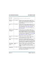
Rack #: LVPS 1/2 A (or
B) Low Line
Power Supply (red)
This alarm occurs if LVPS 1A (U2), 1B (U3), 2A (U102), or 2B (U103) is
reporting a low ac input voltage (less than 175 V ac, higher than 90 V ac).
The power supply will limit its associated module’s output.
Rack #: LVPS 1/2 A (or
B) Missing
Power Supply (amber) This alarm occurs if LVPS module 1A (U2), 1B (U3), 2A (U102), or 2B (U103)
has been removed. Install an operational LVPS module. The alarm may
persist for several seconds after replacing an LVPS module, before the LVPS
module is recognized. If the alarm persists after one minute, try reseating
the LVPS module. This alarm may also be caused by an ac power loss to the
LVPS module. This alarm only occurs if the system is configured to use LVPS
1A, 1B, or 2A, 2B, as applicable (see
) of the Operations & Maintenance Manual.
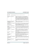
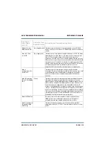
Rack #: Module
Extraction Shutback
Power Amplifier (red) This alarm occurs if the RF power module is removed without first being
inhibited via its front panel switch. Try reseating the RF power module. If
the alarm persists, suspect a fault with circuitry on the associated module
control/interface PWB.
Rack #: Reject Fan
Volts Fail (Rej Fan V
Fail)
Power Supply (red)
This alarm occurs if the fan voltage for the module is 10% high or 10% low
from the expected value. This may be the result of a fault with the
associated circuit on the module control/interface PWB (A3).
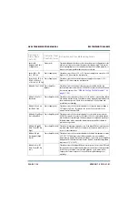
Device and
Alarm Name
(AUI, UI)
Controller Front
Panel LED (color)
Description and Troubleshooting Action
Summary of Contents for GV60
Page 2: ......
Page 4: ......
Page 8: ...GV60 TROUBLESHOOTING MANUAL PAGE 4 VIII VERSION 1 0 2018 01 01 ...
Page 102: ...GV60 TROUBLESHOOTING MANUAL PARTS LISTS PAGE 4 2 12 VERSION 1 0 2018 01 01 ...
Page 463: ...VERSION 1 0 2018 01 01 MD 17 Figure MD 17 NAPA31C Power Amplifier PWB Q1 ...
Page 475: ...GV60 TROUBLESHOOTING MANUAL LIST OF TERMS PAGE 4 6 2 VERSION 1 0 2018 01 01 ...
Page 476: ......


