GV60 TROUBLESHOOTING MANUAL
RESPONDING TO ALARMS
VERSION 1.0 2018-01-01
PAGE 4.1.31
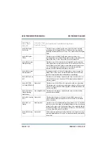
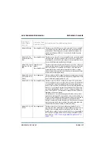
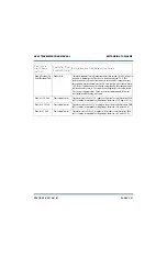
Rack #: Residual PA
Volts (Residual PA V)
Exciter (red)
This alarm indicates that after the transmitter has turned off its RF output, it
is unable to discharge the PA volts to a level that is below 10 V. This
condition will not allow the transmitter to turn on its RF output; however
the condition will be cleared once the PA volts reaches a level that is below
10 V. If the condition cannot be cleared automatically, the transmitter will
still be allowed to turn on. This condition will typically occur with a failed
PA or power supply module. Check for associated alarms and follow the
associated troubleshooting procedure.
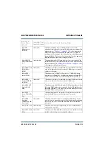
Rack #: +15V Fail
Power Supply (red)
This alarm occurs if the +15 V supply on the module control/interface PWB
(A3) is outside its acceptable voltage range (b13.5 and +16.5 V).
Rack #: +3.3V Fail
Power Supply (red)
This alarm occurs if the +3.3 V supply on the module control/interface PWB
(A3) is outside its acceptable voltage range (b3.0 and +3.6 V).
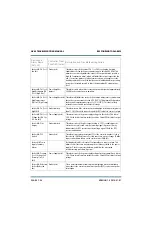
Rack #: +5V Fail
Power Supply (red)
This alarm occurs if the +5 V supply on the module control/interface PWB
(A3) is outside its acceptable voltage range (b4.5 and +5.5 V).
Device and
Alarm Name
(AUI, UI)
Controller Front
Panel LED (color)
Description and Troubleshooting Action
Summary of Contents for GV60
Page 2: ......
Page 4: ......
Page 8: ...GV60 TROUBLESHOOTING MANUAL PAGE 4 VIII VERSION 1 0 2018 01 01 ...
Page 102: ...GV60 TROUBLESHOOTING MANUAL PARTS LISTS PAGE 4 2 12 VERSION 1 0 2018 01 01 ...
Page 463: ...VERSION 1 0 2018 01 01 MD 17 Figure MD 17 NAPA31C Power Amplifier PWB Q1 ...
Page 475: ...GV60 TROUBLESHOOTING MANUAL LIST OF TERMS PAGE 4 6 2 VERSION 1 0 2018 01 01 ...
Page 476: ......


