GV60 TROUBLESHOOTING MANUAL
RESPONDING TO ALARMS
PAGE 4.1.74
VERSION 1.0 2018-01-01
Pre-Amplifier PWB Replacement - Exciter
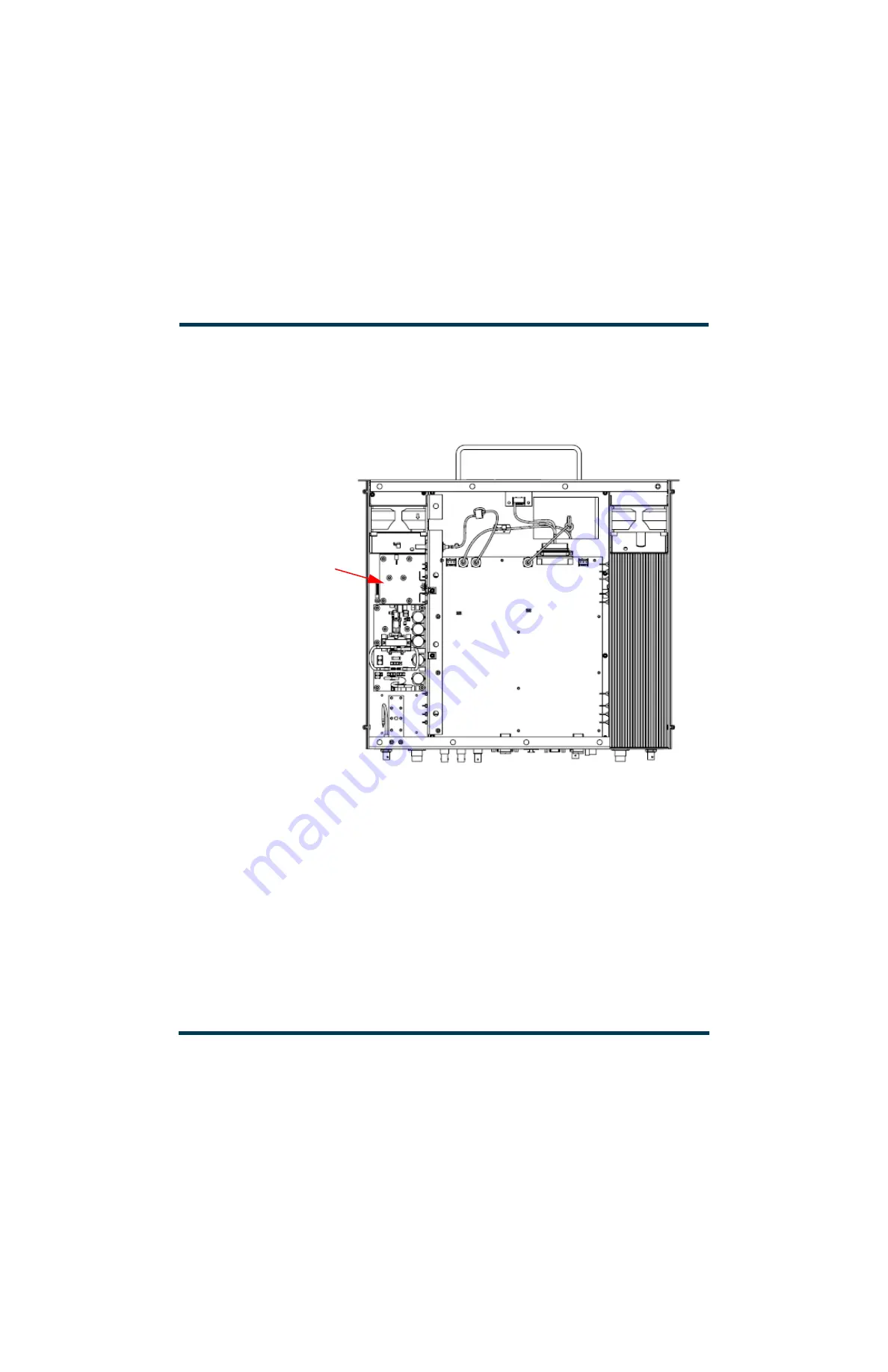
Using
as guides, replace the exciter module’s pre-
amplifier PWB (A5A3) as follows:.
Figure 4.1.29: Pre-Amplifier PWB Location - Exciter
1.
Remove the exciter module (A5) as described in
“Exciter Replacement” on page 4.1.69
.
2.
Place the exciter module on a suitable work surface. Remove the top cover or bottom cover
depending on which pre-amplifier (1 or 2) needs to be replaced. Retain hardware.
3.
Loosen the plastic nut that secures voltage regulator U1 to its heatsink (see
). Remove and retain the plastic nut and washer.
4.
Unsolder U1’s three mounting leads from the pre-amplifier PWB and carefully pull it away from its
heatsink. This should also allow you to remove the heatsink and insulator for U1. Retain U1, its
heatsink and its insulator.
5.
Unsolder and remove the four solder connections to the defective pre-amplifier PWB. They include
three 20 AWG links (to pads B, C and D) and a coaxial connection (to pads A and E).
TOP VIEW
(cover removed)
PRE-AMPLIFIER 2 PWB
A6
NOTE:
Pre-amplifier 1 (A3) is located on the
opposite side of the exciter. See
Summary of Contents for GV60
Page 2: ......
Page 4: ......
Page 8: ...GV60 TROUBLESHOOTING MANUAL PAGE 4 VIII VERSION 1 0 2018 01 01 ...
Page 102: ...GV60 TROUBLESHOOTING MANUAL PARTS LISTS PAGE 4 2 12 VERSION 1 0 2018 01 01 ...
Page 463: ...VERSION 1 0 2018 01 01 MD 17 Figure MD 17 NAPA31C Power Amplifier PWB Q1 ...
Page 475: ...GV60 TROUBLESHOOTING MANUAL LIST OF TERMS PAGE 4 6 2 VERSION 1 0 2018 01 01 ...
Page 476: ......


