Page 9
4.
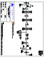
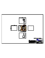
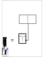
While using the factory mockup photos as a guide, trace through the RF
schematic for the ATU system, starting at the RF input, and working through to
the RF output. As the components are identified in the RF schematic, the
corresponding location of the component should be identified in the component
layout drawing, and also observed in the corresponding photo(s).
5.
During the actual installation of the components, which is covered in the
following sections, the factory mockup photos should be referred to as needed for
clarification.
D. Installation of Floor-Mounted RF components
1.
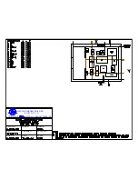
Refer again to the ATU floor layout drawing, showing the correct placement of all
the RF components.
2.
Make sure all of the mounting holes were drilled to the correct depth for
anchoring the floor-mounted components, and that all the holes have been cleared
of debris using the vacuum cleaner.
3.
When all the holes have been drilled and vacuumed, install the hardware anchors
into the holes in the concrete for each component panel. To ensure that all of the
holes have been included, do this for only one component panel at a time.
4.
Find all the floor-mounted component panels, as labeled on the drawing. Make
sure all insulators and hardware are securely mounted on each component panel.
Install each component panel as shown in the ATU floor layout drawing. Make
sure each component is oriented in the correct direction (refer to photos as
needed).
5.
Note: Do not install any of the capacitors yet. Only install the component
panels at this time. The capacitors will be mounted on these panels in a later
step.
6.
The correct orientation for each component may be determined by carefully
examining the photographs from the factory mockup of the ATU. The final
verification of the correct position and orientation will be made when the
interconnecting copper pipe sections are installed. In order for the copper pipe
sections to mate properly with the components, the components must be
positioned and oriented correctly.
Summary of Contents for NX100
Page 2: ......
Page 15: ...Page 13...
Page 16: ...Page 14...
Page 17: ......
Page 20: ......
Page 21: ......
Page 23: ......


