Page 12
G. Installation of Auxiliary Equipment
1.
Locate the remote meters for the input and output RF current.
2.
Each meter has been calibrated together with its toroid and cable as a matched set.
Use the serial numbers to match each meter with the correct transformer.
3.
For each meter/toroid combination, temporarily route the cable that connects them
to make sure that the cable routing allows a proper connection on each end
without causing stretching or strain of the cable. When a suitable routing has
been determined, the cable can then be routed and secured properly. Note that the
cable must remain tight against the copper wall/floor or in grounded conduit for
protection.
4.
Mount the meters in the correct hole marked by the labels on the front of the
safety screen wall.
5.
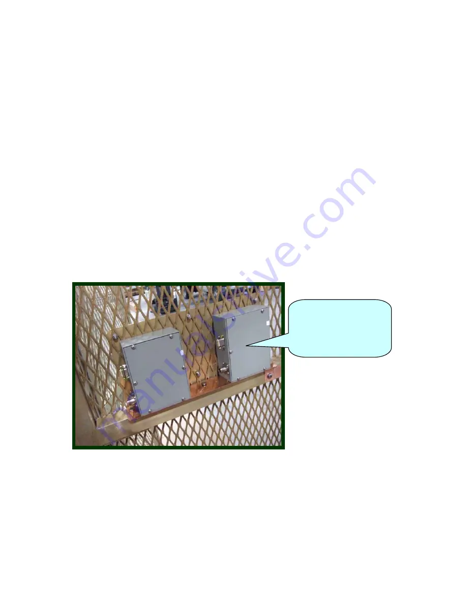
The factory mockup photos will show the locations of the meters.
6.
A typical example photo showing the meters mounted is below. This shows the
meters as seen from inside the RF compartment. The meters are to be read and
operated from the safe side of the safety screen wall.
Figure 4: Rear view of meters
This completes the ATU network installation.
Refer questions to Kintronic Labs, Inc. Engineering Dept.
Close-up of back of
RF current meters
from the inside of
safety screen wall
Summary of Contents for NX100
Page 2: ......
Page 15: ...Page 13...
Page 16: ...Page 14...
Page 17: ......
Page 20: ......
Page 21: ......
Page 23: ......


