NX50 Troubleshooting Manual
Wiring/connector lists
Page 3-8
Issue 6.0 2019-04-01
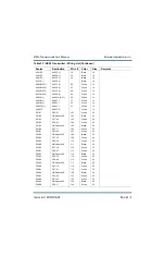
T1-LOAD1
T1A1XF1-1
400
White
12
T1-LOAD0
T1A1XF1-3
401
White
12
T1A1U1-2
T1A1XF1-1
402
White
14
T1A1U2-2
T1-LOAD2
403
White
14
T1A1U3-2
T1-LOAD3
404
White
14
T1-LOAD1
A48U1-AC1
Black
2
T1-LOAD2
A48U1-AC2
Black
2
T1-LOAD3
A48U1-AC3
Black
2
T1-LINE1
Line 1-2
-
Black
1/0
T1-LINE1
Line 1-2
-
Black
1/0
T1-LINE2
Line 2-2
-
Black
1/0
T1-LINE2
Line 2-2
-
Black
1/0
T1-LINE3
Line 3-2
-
Black
1/0
T1-LINE3
Line 3-2
-
Black
1/0
Fr Door GND
GND 1
-
Braid
14
Rr Door GND
GND 2
-
Braid
14
Ex Door GND
GND 3
-
Braid
14
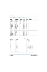
Table 3.4: NX50 Transmitter - Connector Mating Information
Connector
Mate
Note
A41E1
C1E1
Voltage probe
E1
E1
Butt splice
E2
E2
Butt splice
E3
A6E1
E4
A6E2
P1
A35J1
Fan Tray
P10
A6J14
To Rack Interface PWB
P11
A6J15
To Rack Interface PWB
P12
A6J6
To Rack Interface PWB
P13
A6J7
To Rack Interface PWB
P14
A11A1J1
To Control / Display PWB
P15
A8J9
To PDM Distribution
P16
U2J1
DC Current probe
P17
A11A1J3B
To Control / Display PWB
Table 3.3: NX50 Transmitter - Wiring List (Continued)
Source
Destination
Wire #
Color
Size
Remarks
Summary of Contents for NX50
Page 2: ......
Page 4: ......
Page 8: ...NX50 Troubleshooting Manual Page viii Issue 6 0 2019 04 01...
Page 10: ...NX50 Troubleshooting Manual Page x Issue 6 0 2019 04 01...
Page 108: ...NX50 Troubleshooting Manual Responding to alarms Page 1 98 Issue 6 0 2019 04 01...
Page 153: ...NX50 Troubleshooting Manual Reading Electrical Schematics Page 4 6 Issue 6 0 2019 04 01...
Page 184: ...Issue 6 0 2019 04 01 MD 4 Figure MD 4 NAPI95A 01 Power Module Interface PWB...
Page 188: ...Issue 6 0 2019 04 01 MD 8 Figure MD 8 NAPI106 Remote Interface PWB...
Page 192: ...Issue 6 0 2019 04 01 MD 12 Figure MD 12 NAPI98 RF Drive Distribution PWB...
Page 198: ...Issue 6 0 2019 04 01 MD 18 Figure MD 18 Fan Tray Assembly 207 8133 B1 B2 J1 AIR FLOW AIR FLOW...
Page 201: ...Issue 6 0 2019 04 01 MD 21 Figure MD 21 NAFP106B 01 Directional Coupler A1 DETAIL...
Page 204: ......

