NX50 Troubleshooting Manual
Responding to alarms
Page 1-44
Issue 6.0 2019-04-01
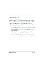
Controller: Interlock Open
A
Controller: Interlock Open
alarm indicates an external interlock is open. The transmitter’s
RF output will be inhibited.
The external interlock input is wired to the control/interface PWB by the end user and
triggered by the conditions that they set (e.g., the state of the door to the transmitter room).
The circuit can be configured as single-ended (internal power supply) or differential (external
power supply), using user-provided shorting jumpers on terminal block TB1 (see
of the Pre-Installation Manual).
1. Gain access to the control/exciter panel (A11) (see
the control cabinet’s front door.
2. Connect a digital multimeter (set to measure dc) between TB1-2 and TB1-3 of the
control/interface PWB.
• If the measured dc voltage is less than 10 V between TB1-2 and TB1-3, the external
interlock circuit is open (normally caused by an open interlock switch). Check for
external causes.
• If the measured dc voltage is greater than 10 V between TB1-2 and TB1-3, the
external interlock circuit is intact and the probable cause of the alarm is a defective
monitoring circuit. Suspect the control/interface PWB and if necessary, replace it
(see
“Control/interface PWB replacement” on page 1-64
).
Summary of Contents for NX50
Page 2: ......
Page 4: ......
Page 8: ...NX50 Troubleshooting Manual Page viii Issue 6 0 2019 04 01...
Page 10: ...NX50 Troubleshooting Manual Page x Issue 6 0 2019 04 01...
Page 108: ...NX50 Troubleshooting Manual Responding to alarms Page 1 98 Issue 6 0 2019 04 01...
Page 153: ...NX50 Troubleshooting Manual Reading Electrical Schematics Page 4 6 Issue 6 0 2019 04 01...
Page 184: ...Issue 6 0 2019 04 01 MD 4 Figure MD 4 NAPI95A 01 Power Module Interface PWB...
Page 188: ...Issue 6 0 2019 04 01 MD 8 Figure MD 8 NAPI106 Remote Interface PWB...
Page 192: ...Issue 6 0 2019 04 01 MD 12 Figure MD 12 NAPI98 RF Drive Distribution PWB...
Page 198: ...Issue 6 0 2019 04 01 MD 18 Figure MD 18 Fan Tray Assembly 207 8133 B1 B2 J1 AIR FLOW AIR FLOW...
Page 201: ...Issue 6 0 2019 04 01 MD 21 Figure MD 21 NAFP106B 01 Directional Coupler A1 DETAIL...
Page 204: ......


