NX50 Troubleshooting Manual
Responding to alarms
Page 1-78
Issue 6.0 2019-04-01
SCR Rectifier Inspection/Replacement
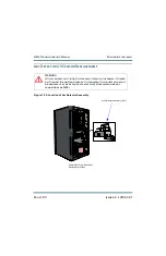
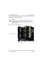
Figure 1.18: Location of SCR Rectifier Assembly and its Cooling Fans
1. Turn off
(disable and lock out)
the ac power at the source.
Open the
rear door verify
the
six
ac indicator LEDs are off (amber when on). Next verify
the
green dc indicator
LEDs on the power module interface PWBs are off indicating the capacitors are
discharged. For additional safety, measure the dc voltage across the + and - terminals
of any of the large, electrolytic capacitors on the floor of the cabinet. There should be
little or no voltage.
WARNING
:
Lethal voltages exist inside the transmitter when the power is turned
on. Turn off the power at the source and verify the 20 bright green
LEDs on the power module interface PWBs are off before removing
any connections or PWBs.
Back Door and Side Panel
Removed for Clarity
Electrolytic Capacitors
Ac Indicator LEDs
A48A1
Terminal Block TB1
Cooling Fan 2
SCR Rectifier
Assembly A48
Line 1, Line 2, Line 3
Connections
DC (+) and DC (-)
Connections
Cooling Fan 1
Summary of Contents for NX50
Page 2: ......
Page 4: ......
Page 8: ...NX50 Troubleshooting Manual Page viii Issue 6 0 2019 04 01...
Page 10: ...NX50 Troubleshooting Manual Page x Issue 6 0 2019 04 01...
Page 108: ...NX50 Troubleshooting Manual Responding to alarms Page 1 98 Issue 6 0 2019 04 01...
Page 153: ...NX50 Troubleshooting Manual Reading Electrical Schematics Page 4 6 Issue 6 0 2019 04 01...
Page 184: ...Issue 6 0 2019 04 01 MD 4 Figure MD 4 NAPI95A 01 Power Module Interface PWB...
Page 188: ...Issue 6 0 2019 04 01 MD 8 Figure MD 8 NAPI106 Remote Interface PWB...
Page 192: ...Issue 6 0 2019 04 01 MD 12 Figure MD 12 NAPI98 RF Drive Distribution PWB...
Page 198: ...Issue 6 0 2019 04 01 MD 18 Figure MD 18 Fan Tray Assembly 207 8133 B1 B2 J1 AIR FLOW AIR FLOW...
Page 201: ...Issue 6 0 2019 04 01 MD 21 Figure MD 21 NAFP106B 01 Directional Coupler A1 DETAIL...
Page 204: ......


