background image

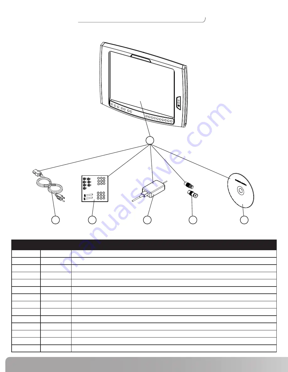
Exploded View

LCD Monitor Kit


REF#

PART#

DESCRIPTION

1

001-1924

LCD Monitor with Accessories  (US)

1

001-1992

LCD Monitor with Accessories  (Euro)

1

001-2013

LCD Monitor with Accessories  (Australia)

1

002-3782

LCD Monitor, DT with Accessories  (Digital)

2

001-1922

Power Cord  (US)

2

001-2015

Power Cord  (Continental)

2

001-2019

Power Cord  (Australia)

2

001-2017

Power Cord  (UK/Ireland)

3

001-1938

Hardware Kit

4

000-8010

Power Brick

4

002-0387

LCD, DT Power Brick (Digital)

5

001-1995

European Adapter Kit  (Europe/Australia Only)

6

001-1923

Owners Manual  (CD ROM)

6

001-7167

Owners Manual (Digital CD ROM)

1

2

3

4

5

6

Summary of Contents for Be Strong. NV915

Page 1: ...Be Strong Model NV915 P N 001 2032 Rev B 08 13 2007 NV915 LCD Monitor Service Manual...

Page 2: ...s 5 Location of Safety Warning Labels 6 Exploded Views and Parts Lists 7 Troubleshooting 13 Replacing Headphone Jack 14 Replacing Keypad 15 Replacing LCD Monitor M Series Bracket 17 Replacing LCD Moni...

Page 3: ...r installation If this equipment does cause unacceptable interference to radio and television reception which can be determined by turning the equipment off and on the user is encouraged to try to cor...

Page 4: ...ources Do not place heavy articles on or step on the LCD Monitor The product should be installed in a clean and dry place If you detect any smoke unusual noise or smell disconnect the electric power a...

Page 5: ...rences and 2 This device must accept any interference received including interference that may cause undesired operation The LCDTV Monitor NV915 000N Model bears the CSA Mark shown with adjacent indic...

Page 6: ...Safety Warning Labels The following safety warnings are located on the NV915 LCD Monitor Please read all safety precautions and warning information prior to using your product...

Page 7: ...eries Bracket Kit REF PART DESCRIPTION 1 001 1915 M Series Bracket Kit Complete 2 001 1894 Console Spacer 3 001 1959 M Series Bracket Kit Installation Manual 4 001 1944 M Series Replacement Hardware K...

Page 8: ...2 3782 LCD Monitor DT with Accessories Digital 2 001 1922 Power Cord US 2 001 2015 Power Cord Continental 2 001 2019 Power Cord Australia 2 001 2017 Power Cord UK Ireland 3 001 1938 Hardware Kit 4 000...

Page 9: ...Nautilus NV915 Service Manual Exploded View REF PART DESCRIPTION 1 001 2033 Front Keypad 2 001 1945 Earphone Jack 3 001 1997 Back Cover LCD Monitor Components 3 2 1...

Page 10: ...PART DESCRIPTION 1 001 1948 T Series Bracket Kit Complete 2 001 1960 T Series Bracket Kit Installation Manual 3 001 1955 T Series Replacement Hardware Kit Use if replacement Hardware is needed 1 T Se...

Page 11: ...ded View Remote Controls Wired Remote Wireless Remote REF PART DESCRIPTION 1 001 1939 Wireless Remote Kit US 1 001 2081 Wireless Remote Kit International 1 002 3785 Wireless Remote Kit US Digital 2 00...

Page 12: ...Replacement Kit 2 001 1934 Upright Assembly 3 001 1851 Adjustable Mast Assembly 4 001 1935 Base Assembly 5 001 2049 Stabilizer B 6 001 2050 Stabilizer A 7 001 2036 Stand Assembly Instruction Manual 8...

Page 13: ...ll outlet Press POWER button on remote Black Background Only Make sure the mode is set toTV and not PC or Video S Video when using a coaxial cable input source Interference or Shaky Display Other appl...

Page 14: ...ove the Decal covering the Headphone Jack Figure A 2 Use a Phillps Head Screwdriver to remove the two screws securing the jack Figure B 3 Carefully remove the Headphone Jack from the LCD Monitor Figur...

Page 15: ...ve the Back Cover of the LCD Monitor Figure A 2 Carefully pull the Ribbon Cable out of the connector Figure B C 3 Gently lay the LCD on it s back and peel off the old Keypad Figure D 4 Remove the old...

Page 16: ...the Adhesive Backing Figure G 7 Position the Keypad on the plastic and firmly press into place Figure H I 8 Turn the LCD over and insert the Ribbon Cable into the connector Figure J 9 Replace the Bac...

Page 17: ...E Two longer screws used on the raised portion of the LCD Monitor Back cover Detail A Figure B Bracket Back Cover Longer screws used here Figure A Detail A Replacing LCD Monitor Replacing M Series mas...

Page 18: ...from the LCD Monitor Power Antenna NOTE International version will have Coaxial Connection Adapter International Coaxial Adapters Optional Wired Remote wires Replacing LCD Monitor Replacing M Series...

Page 19: ...olts on each side of the Bracket Figure A LCD Monitor Bracket Replacing LCD Monitor Replacing M Series mast mount LCD Monitor continued M10 Allen Bolt Step 4 Prepare to install the new LCD Monitor Too...

Page 20: ...Re Install the M10 Allen Bolts and Lock Washers 5 3 Position the LCD Monitor Figure B C Note The Monitor has a 30 range of viewing angles Position at your discretion Figure B C 5 4 Completely tighten...

Page 21: ...to the LCD Bracket to avoid accidental disconnection NOTE If you are using the optional Wired Remote attach the end labeled LCDTV at this time Refer to Wired Remote Installation Manual for more infor...

Page 22: ...Cover of the Bracket Figure A and the LCD Monitor Figure B NOTE Use the two longer screws on the raised portion of the LCD Monitor Back cover Detail A Figure A Bracket Back Cover Use longer screws her...

Page 23: ...r of the LCD Monitor Figure A and the Bracket Figure B NOTE Two longer screws used on the raised portion of the LCD Monitor Back cover Detail A Figure B Bracket Back Cover Use longer screws here Figur...

Page 24: ...wires from the LCD Monitor Replacing LCD Monitor ReplacingT Series LCD Monitor continued Power Antenna NOTE International version will have Coaxial Connection Adapter International Coaxial Adapters O...

Page 25: ...en Bolts on each side of the Bracket Figure A Detail A LCD Monitor Bracket M10 Allen Bolt Replacing LCD Monitor ReplacingT Series LCD Monitor continued Step 4 Prepare to install the new LCD Monitor To...

Page 26: ...A 5 2 Re Install the M10 Allen Bolts and Lock washers 5 3 Position the LCD Monitor Figure B C Note The Monitor has a 30 range of viewing angles Position at your discretion Figure B C 5 4 Completely ti...

Page 27: ...to the LCD Bracket to avoid accidental disconnection NOTE If you are using the optional Wired Remote attach the end labeled LCDTV at this time Refer to Wired Remote Installation Manual for more infor...

Page 28: ...Covers Tools Needed Phillips Head Screwdriver 7 1 Replace the Back Cover of the Bracket Figure A and the LCD Monitor Figure B NOTE Use the two longer screws on the raised portion of the LCD Monitor B...

Page 29: ...Nautilus International S A Rue Jean Prouv 6 1762 Givisiez Switzerland Tel 41 26 460 77 77 Fax 41 26 460 77 70 Email technics nautilus com INTERNATIONAL OFFICES SWITZERLAND OFFICE Nautilus Switzerland...

Page 30: ...l rights reserved Nautilus the Nautilus logo and Be Strong are either registered trademarks or trademarks of Nautilus Inc All other marks are either registered trademarks or trademarks of their respec...

Reviews: