1
2.0 ReMoVInG UPRIGHTs
Tools needed:
• Phillips head screw driver
• 5/32 Allen wrench
• 3/4 inch wrench or socket
• 1/2 inch drive Ratchet
• 1/2 inch drive Torque wrench
step 1:
Remove for the four Button head screws at-
taching the console to the Upright weldment,
disconnect the cables and remove the console
from the machine.
step 2:
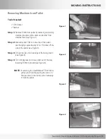
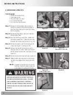
Remove the Rear Step as directed in Section 1:
Removing Rear Step.
step 3:
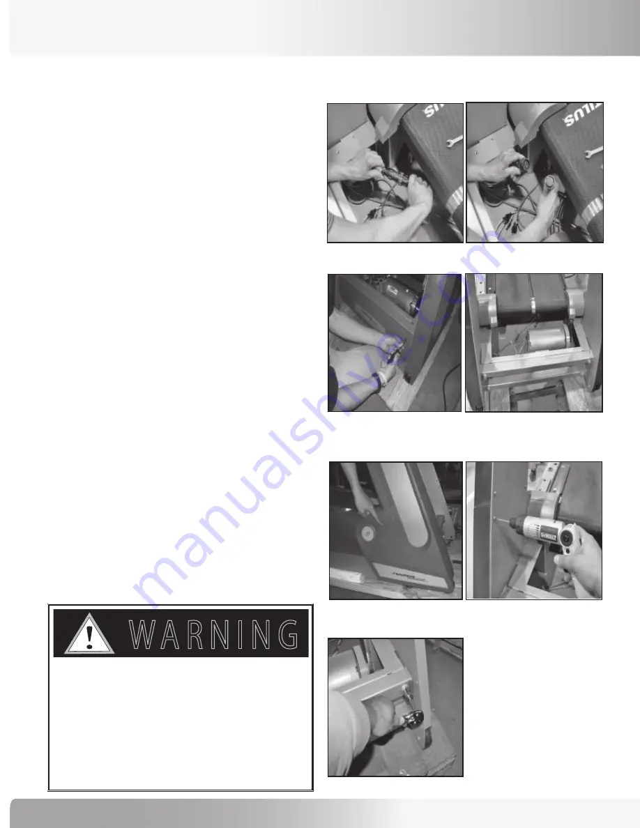
Disconnect the Base Cable (P/N - 17826) from
the Handrail Cable (P/N - 17824) located in the
lower left hand corner (see Figures 2-1 and 2-2).
step 4:
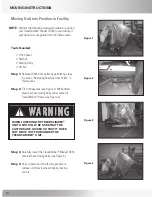
Remove rear plastic cover by loosening six (6)
screws (see Figure 2-3 and Figure 2-4).
step 5:
Remove right and left lower plastic parts by
removing seven (7) screws located on the right
and left upright inside panels (see Figure 2-5 and
Figure 2-6).
step 6:
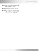
Remove the four (4) upright bolts (see Figure 2-7)
step 7:
Wheel upright structure away to safe location
(wheels are integrated into upright portion of
unit).
noTe:
To replace the upright unit, reverse the
directions.
The four handrail screws are
to be torqued to a setting of 75 ft. lbs.
figure 2-1
figure 2-2
figure 2-3
figure 2-4:
Rear plastic cover off.
figure 2-5:
lower plastic parts.
figure 2-6
figure 2-7
detaching and moving the upright portion oF
this product requires two people! you must
have a minimum oF two people to properly
support the heavy upright structure so the
console does not Fall and cause damage to
the unit.
7 ! 2 . ) . '
! 4 4 % . 4 ) / .
$ ! . ' % 2
)--%$)!4%!#4)/.2%15)2%$
# ! 5 4 ) / .
MoVInG InsTRUcTIons

