background image

29

Heart Rate Control (HRC) Workout

The Heart Rate Control (HRC) program lets you set a heart rate goal for your workout. The program monitors your heart rate 
in beats per minute (BPM) from the Contact Heart Rate (CHR) sensors on the machine or from a Heart Rate Monitor (HRM) 
chest strap.


Note:

   The console must be able to read the heart rate information from the CHR sensors or  HRM for the HRC program to 

work correctly.

If you go to the HRC program from your User profile, the Target Heart Rate program uses your age and other user setup 

information to set the Heart Rate Zone values for your workout. If you are a Guest User, the program will use the default values 
for your workout. The console display then gives prompts for you to set up your workout:

1.   Set the workout level: BEGINNER or ADVANCED.
2.   Set the percentage of maximum heart rate: 60–70%, 70–80%, 80–90%.

Consult a physician before you start to exercise in the 80–90% heart rate zone.

3.   Set the Time for the workout. (The default value is 10:00.)

Distance Goal Program

The Distance Goal Program lets you set the total Distance and Pacer Speed for your workout. 
If you go to the Distance Goal program from your User profile, the program will use the Age and Weight values in your User 
profile. If you are a Guest User, the program will use the default values for your workout. The console display then gives 
prompts for you to set up your workout:

1.   Enter the distance with the Increase(

) and Decrease(

) buttons (default is 20 mi/ 20 km). Push START/ENTER

2.   Enter the pacer speed with the Increase(

) and Decrease(

) buttons (default is 25 mph/ 25 km/h). Push START/ENTER.

3.   The workout starts at level 1. To adjust the resistance, use the Increase/Decrease buttons.
4.   The TIME display starts to count up from 00:00.

Results / Cool Down Mode

After a workout the TIME display shows 00:00 and then starts to count up. During this Cool Down period, the Console shows 
the Workout Results and your current Heart Rate. All workouts except Quick Start have a 3-minute Cool Down period. 
The LCD display shows each workout data value for 4 seconds: TIME, DISTANCE, CALORIE, AVG/MPH (KMH), AVG/PWR, 
AVG/HR, MAX/HR. You can use the Increase/Decrease buttons to move through the results manually. The HR display shows 
the current BPM value. 
The Level during Cool Down is based on the Level at the end of the workout:

End Level

Cool Down Level

Level  

  3

1

3  <  Level  

  10

3

10  <  Level

5

You can push STOP to stop the Results display and go back to Power-Up Mode. If there is no RPM or HR signal, the Console 
automatically goes into Sleep Mode.

Summary of Contents for E514c

Page 1: ...ASSEMBLY MANUAL OWNER S MANUAL Manual en Español Latino Americano http www nautilus com E514c ...

Page 2: ...kout 29 Distance Goal Workout 29 Results Cool Down Mode 29 Pausing or Stopping 30 User Statistics 30 Console Setup Mode 31 Maintenance 32 Troubleshooting 35 Table of Contents To validate warranty support keep the original proof of purchase and record the following information Serial Number __________________________ Date of Purchase ____________________ To register your product warranty go to www ...

Page 3: ...mpromise the safety of this machine and will void the warranty If replacement parts are necessary use only genuine Nautilus replacement parts and hardware Failure to use genuine replacement parts can cause a risk to users keep the machine from operating correctly and void the warranty Do not use until the machine has been fully assembled and inspected for correct performance in accordance with the...

Page 4: ...easonable protection against harmful interference in a residential installation This equipment generates uses and can radiate radio frequency energy and if not installed and used in accordance with the instructions may cause harmful interference to radio communications However there is no guarantee that interference will not occur in a particular installation If this equipment does cause harmful i...

Page 5: ...ng 2 pieces lightly lift and look through the bolt holes to help insert the bolt through the holes The assembly requires 2 people Some axles contain oil Use caution to avoid staining clothes or carpet Maximum User Weight 300 lbs 136 kg Power Requirements Operational Voltage Operational Voltage 9VDC Operating Current 1500 mA Regulatory Approvals AC Power Adapter UL listed CSA certified or equivalen...

Page 6: ...t Handlebar Arm 3 1 Rear Stabilizer 13 1 Left Handlebar Arm 4 1 Front Stabilizer 14 1 Lower Left Handlebar Arm 5 1 Console Mast 15 1 Lower Right Handlebar Arm 6 1 Transport Handle 16 1 Static Handlebar 7 2 Rail 17 1 Console 8 1 Right Pedal 18 1 AC Adapter 9 1 Left Pedal 19 1 Arm Pivot Rod 10 1 Right Leg 20 1 MP3 Cord not shown PARTS 7 6 3 4 1 5 16 17 11 10 14 15 19 8 2 13 12 18 9 ...

Page 7: ...x20L Thread Lock M 2 Cotter Pin E 4 Button Head Hex Screw M8x25L Thread Lock N 2 Wave Washer F 2 Phillips Head Screw M5x20L O 4 Lock Washer M8 Black G 8 Button Head Hex Screw M8x20L P 6 Cover H 2 Button Head Hex Screw M8x20L Thread Lock Q 6 Button Head Hex Screw M8x25L I 12 Button Head Hex Screw M8x15L R 6 Flat Head Hex Screw M8x25L Thread Lock recommended HARDWARE TOOLs A B C D E F G H I J L K M ...

Page 8: ...8 1 Attach Rear Stabilizer and Transport Handle to Rails ASSEMBLY 2 Attach Rail Assembly and Front Stabilizer to Frame 6 mm C X8 7 6 B I 3 K J X2 7 6 mm R 4 1 X6 ...

Page 9: ...9 3 Connect the Lower Console Cables NOTICE Align the clips on the cable connectors and make sure the connectors lock Do not crimp Console Cable 5 ...

Page 10: ...10 4 Attach Console Mast to Frame Assembly NOTICE Do not crimp Console Cable 6 mm Q P B C X6 ...

Page 11: ...tach the Static Handlebar NOTICE Do not crimp Console Cable 6 Remove Hardware from Console NOTICE Do not crimp the cables Hardware is pre installed on Console and not on Hardware Card 2 17 X4 6 mm X2 C 16 E B ...

Page 12: ...Cables and Attach Console to Frame Assembly NOTICE Align the clips on the cable connectors and make sure the connectors lock Do not crimp the cables Hardware is pre installed on Console and not on Hardware Card 2 X4 ...

Page 13: ...13 8 Attach Legs to Frame Assembly A 11 10 O D L X2 ...

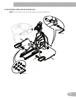
Page 14: ...14 9 Attach Lower Handlebar Arms X2 L 14 15 D O A 19 N X2 ...

Page 15: ...15 10 Attach Pedals to Rails and Lower Handlebar Arms NOTICE Be sure the key on the Cotter Pin engages the Lower Handlebar Arm X2 C 8 9 X2 6 mm 6 mm M B E C B I H B C I B C 2 2 ...

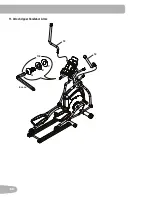
Page 16: ...16 11 Attach Upper Handlebar Arms 13 X8 6 mm G 12 B C ...

Page 17: ... Final Inspection Inspect your machine to ensure that all hardware is tight and components are properly assembled Do not use until the machine has been fully assembled and inspected for correct performance in accordance with the Owner s Manual 18 ...

Page 18: ...ions can affect the computer operation Leveling the Machine The machine needs to be leveled if your workout area is uneven or if the Rail Assembly is slightly off the floor To adjust 1 Place the machine in your workout area 2 Safely stand on the back of the Rail Assembly for approximately 20 seconds 3 Step off the machine 4 Loosen the locking wing nuts and adjust the levelers until they all contac...

Page 19: ...ormation Maximum user weight limit 300 lbs 136 kg Do not use if you are over this weight This machine is for home use only Do not wear loose clothing or jewelry This machine contains moving parts Do not put fingers or other objects into moving parts of the exercise equipment Set up and operate this machine on a solid level horizontal surface Make the Foot Pedals stable before you step on them Use ...

Page 20: ...le B Contact Heart Rate CHR Sensors J Foot Pedal C Console K Media Tray D Swing Arm Handlebars L Fan E Transport Roller M Speakers F AC Adapter Plug N MP3 Input G Leveler O Water Bottle Holder H Rail FEATURES B A C D E G J H F I G O K L M N ...

Page 21: ...Data Program Display The Program Display shows the name of the program selection and the grid display area shows the course profile for the program Each column in the profile shows one interval workout segment The higher the column the higher the resistance level The flashing column shows your current interval Time Interval The TIME display field shows the time count of the workout for 6 seconds a...

Page 22: ... not work with this equip ment If you have a pacemaker or other implanted electronic device consult your doctor before using a wireless chest strap or other telemetric heart rate monitor Contact Heart Rate Sensors Contact Heart Rate CHR sensors send your heart rate signals to the Console The CHR sensors are the stainless steel parts of the Handlebars To use put your hands comfortably around the se...

Page 23: ...r lower than what is shown The most efficient procedure to burn fat during exercise is to start at a slow pace and gradually increase your intensity until your heart rate reaches between 60 85 of your maximum heart rate Continue at that pace keeping your heart rate in that target zone for over 20 minutes The longer you maintain your target heart rate the more fat your body will burn The graph is a...

Page 24: ...nto the opposite Pedal To dismount your fitness machine 1 Move the Pedal you want to dismount from to the lowest position and bring the machine to a complete stop This machine is not equipped with a free wheel Pedal speed should be reduced in a controlled manner 2 Grasp the Static Handlebars under the Console to steady yourself 3 With your weight on the dismount foot bring the opposite foot over t...

Page 25: ...and on the machine 2 Push the START ENTER button 3 Use the Increase or Decrease buttons to select one of the profile programs Push START ENTER to select the profile program 4 Use the Increase and Decrease buttons to adjust the workout time Push START ENTER Note The range of values for TIME is 5 99 minutes the default value is 30 00 5 Use the Increase and Decrease buttons to adjust the resistance l...

Page 26: ...creen Note The Custom workout can be created at a later time by editing the User 8 If you start the Custom Workout setup the Program Display will show the left column workout interval is active by flashing with a default resistance level of 3 Use the Increase Decrease buttons to adjust the resistance level of the active interval Push START ENTER to record the resistance level The next column to th...

Page 27: ... is active by flashing Use the Increase Decrease buttons to adjust the resistance level of the active interval Push START ENTER to record the resistance level The next column to the right becomes active Note The Console display shows the message N of 20 during setup N is the current interval The maximum number of intervals is 20 Push and hold START ENTER to accept the Custom Workout 7 When done pu...

Page 28: ...r profile to calculate your Fitness Score If you are a Guest User the program will use the default values for your workout Start to pedal and hold the Heart Rate Sensors When the test starts the power Watts slowly increases This means you will work harder and as a result your heart rate increases The Watts continues to increase automatically until your heart rate reaches the Test Zone This zone is...

Page 29: ...ofile the program will use the Age and Weight values in your User profile If you are a Guest User the program will use the default values for your workout The console display then gives prompts for you to set up your workout 1 Enter the distance with the Increase and Decrease buttons default is 20 mi 20 km Push START ENTER 2 Enter the pacer speed with the Increase and Decrease buttons default is 2...

Page 30: ...99999 The Statistics option in the User profile menu lets you look at the recorded data or delete it 1 Push the My Nautilus button at the Power Up Mode screen The Console display shows the User Profiles 2 Use the Increase and Decrease buttons to select a User profile and push START ENTER to make your selection 3 After you select the User profile option you have two options VIEW STATS and WORKOUT U...

Page 31: ... Machine Type option Push the Increase Decrease buttons to change between ELLIPTICAL and BIKE 5 Push START ENTER to set For the next option push the Increase button 6 The Console display shows the Brightness prompt Push START ENTER to start the brightness option Push the Increase Decrease buttons to change the backlight levels from 1 lowest to 5 highest 7 Push START ENTER to set For the next optio...

Page 32: ...g maintaining or repairing the machine Place the power cord in a secure location Daily Before each use examine the exercise machine for loose broken damaged or worn parts Do not use if found in this condition Repair or replace all parts at the first sign of wear or damage After each workout use a damp cloth to wipe your machine and Console free of sweat Note Avoid excessive moisture on the Console...

Page 33: ...33 Maintenance Parts A C F B G H J I J K O R Q P N N P Q X Z S T Y AA BB S Y DD CC K EE JJ II FF GG HH D E U L W M V ...

Page 34: ... E Console Cable Lower Q Rail CC Handlebar Arm Upper Left F Arm Pivot Rod R Transport Handle DD Fly Wheel G Handlebar Arm Upper Right S Leveler EE Brake Assembly H Handlebar Arm Lower Right T Rear Stabilizer FF Servo Motor I Shroud Right U Leg Left GG Drive Belt J Shroud Crank V Pedal Arm Left HH Pulley K Crank Arm W Pedal Left II AC Adapter Plug L Pedal Right X AC Power Adapter JJ Speed Sensor Ma...

Page 35: ...lebars and cable to Console are secure and undamaged Sensor grip Be sure hands are centered on HR sensors Hands must be kept still with relatively equal pressure applied to each side Dry or calloused hands Sensors may have difficulty with dried out or calloused hands A conductive electrode cream such as Signa Crème or Buh Bump can help make better conduct These are available on the web or at medic...

Page 36: ...atch on connector should line up and snap into place Reset machine Unplug unit from electrical outlet for 3 minutes Reconnect to outlet Check magnet position requires shroud removal Magnet should be in place on pulley Check Speed Sensor Contact Customer Care for further assistance Fan will not turn on or will not turn off Check data cable integrity All wires in cable should be intact If any are cu...

Page 37: ...ural disasters power surges A machine placed or used in a commercial or institutional setting This includes gyms corporations work places clubs fitness centers and any public or private entity that has a machine for use by its members customers employees or affiliates Damage caused by exceeding maximum user weights as defined in the Product s Owner s manual or warning label Damage due to normal us...

Page 38: ...Nautilus Bowflex Schwinn Fitness Universal 8001054 111512 B EN ...

Reviews: