background image

Page 3

5. 

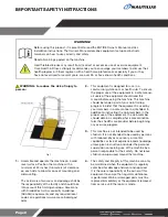
All equipment MUST be secured (bolted and 
tightened) to a solid, level surface, using all of 
the anchoring holes provided, to stabilize and 
eliminate rocking or tipping over. Shim any 
mounting surface that does not rest thoroughly 
on the fl oor using fl at washers, DO NOT force the 
foot to contact the ground with anchors.

Fasteners must have a minimum of 500 lbs. 
tensile capacity, be a bolt of grade 2 or better 
and be installed per the bolt manufacturer’s 
specifi cations.

WARNING:

 Due to the wide variety of fl ooring 

on which equipment may be anchored or installed 
and differences in applicable local building codes, 
Core Health & Fitness is not responsible for any 
damage to the fl ooring that may result due to 
anchoring or installing equipment to the fl oor and 
for compliance with local building codes. Only 
licensed contractors or certifi ed installers should 
be used to insure proper anchoring, installation, 
and compliance with local building code.

6. 

Do not exceed the maximum allowable user 
weight limit of:

•  350 lbs. (160 kg.)

7. 

It is the purchaser’s sole responsibility to properly 
instruct its end users and supervising personnel 
as to the proper operating procedures of all 
equipment. 

8. 

 Caution: unit is heavy and requires two people 

for assembly.

SAVE THESE INSTRUCTIONS

Summary of Contents for HDP6D-LFHR

Page 1: ...ASSEMBLY MANUAL CORE HEALTH FITNESS HDP6D LFHR...

Page 2: ...ulations www access board gov ada 2 This equipment is designed for use in a commercial gymnasium or health club To ensure the proper use of the equipment in a safe manner all users of the equipment sh...

Page 3: ...t may be anchored or installed and differences in applicable local building codes Core Health Fitness is not responsible for any damage to the ooring that may result due to anchoring or installing equ...

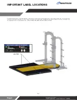
Page 4: ...ufacturing process It is critical that own ers maintain the integrity and placement of these stickers If you nd any stickers missing or damaged the replacement numbers are shown on the support site Se...

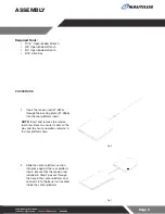
Page 5: ...e no debris remains in the rear platform hole Fig 6 2 Slide the center platform section into place against the rear platform insert Ensure that the tension rod installed in Step 1 passes through the h...

Page 6: ...forms together Fig 8 4 Set the cross member tube into place against the center platform section Fig 9 5 Assemble the tie rod assembly by inserting two 2 tie rod halves into the tie rod coupling and se...

Page 7: ...tions Fig 11 9 Slide the left side trim tube onto the rear tie rod assembly then install the left side frame tube over the ends of the tie rods 10 Repeat Step 9 for the right side trim tube Fig 12 11...

Page 8: ...bracket if the platform is moving during use Follow all safety and building codes when securing the platform to the oor Fig 14 14 Use a 3 4 open ended wrench to secure a platform bracket to the left s...

Page 9: ...sing one 1 piece each of the 1 2 at washer and 1 2 x 1 bolt 18 Repeat Step 17 for the left and right sides Fig 17 19 Install the six 6 absorption pads into the platform assembly Fig 18 20 Install the...

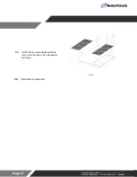
Page 10: ...Page 10 21 Install the textured rubber platform mats onto the top of the absorption pad tops Fig 20 22 Installation is Complete...

Page 11: ...t always runs like new with a Core Advantage Preventative Maintenance or Extended Warranty Package Contact your service manager for more information servicecontracts corehandf com To request access vi...

Page 12: ...ed Star Trac the Star Trac logo and StairMaster are registered trademarks of Core Health Fitness LLC Schwinn and Nautilus are registered trademarks of Nautilus Inc used under license to Core Health Fi...

Reviews: