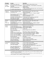
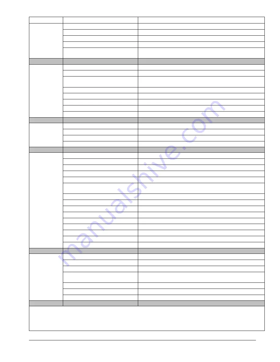
background image

  21 


Problem 

Cause 

Solution 

Dual Circuit  

Cords on the same circuit 

Move one cord to outlet on different circuit 

Indicator 

No voltage from one/ both outlets 

Check circuit breakers – Reset breakers or move cords 

Not Lighted 

Light Bad 

Replace Light 


Dual Circuit Indicator Bad 

Replace indicator 


One/Both Outlets Wired wrong 

If hot & neutral sides switched on outlet, machine will work, 
but light will not turn ON. 


Pump-out 

Building circuit breaker tripped. 

Reset breakers or move cords to other outlets 

not working 

Faulty power cord 

Replace cord (AX33) 


Faulty switches or internal wiring 

Check wiring & test switches - Repair as needed * 
(NM5714) 


Pump-out pump faulty 

Replace pump-out pump (AP37) 


Pump-out float switch faulty 

Replace Float Switch 


Float Switch movement restricted 

Clean debris off of Float Switch or adjust float 


Discharge hose restricted 

Un-kink, clean out or replace hose 


Pump-out pump clogged 

Remove and clean out pump 


Vacuum 

Building circuit breaker tripped. 

Reset breakers or move cords to other outlets 

Motor  

Faulty power cord 

Replace cord (AX33) 

not running 

Faulty switches or internal wiring 

Check wiring & test switches - Repair as needed * 


Vacuum motor faulty 

Replace vacuum motor (AV14) 


Loss of  

Vacuum motor faulty 

Replace vacuum motor (AV14) 

Vacuum 

Vacuum motor gasket damaged 

Replace gasket (PA010) 


Recovery tank lid gasket damaged  Replace gasket (NM5718) 


Drain valve open 

Close valve 


Drain valve leaking 

Repair or replace drain valve (PEA11) 


Vacuum motor hoses loose / 
leaking 

Reconnect or replace vacuum motor hoses 


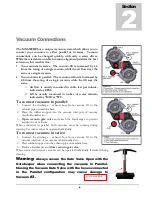
Vacuum Valve in wrong Position 

Check Vacuum Gate Valve Position. – PAGE 8 


Vacuums not connected properly 

See vacuum connection instructions – PAGE 8 


Vacuum hose or tool clogged 

Clean out vacuum hoses and tool 


Vacuum hoses or cuffs leaking 

Replace vacuum hoses, cuffs & connectors as needed 
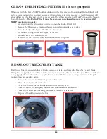
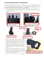
  

Recovery tank full 

Drain tank 


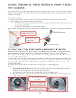
Float shutoff filter clogged 

Clean float shutoff filter 


Float stuck in float shutoff 

Repair or replace float shutoff 


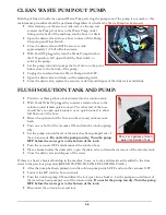
Pump-out Pump faulty 

Repair or replace pump out pump (AP37) 


Recovery tank damaged 

Replace recovery tank 
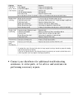
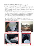


Chemical not  

Solution tank not filling 

Check & repair auto fill assembly 

feeding  

Chemical hose restricted 

Un-kink, shorten, clean out or replace hose  


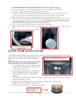
Filter screen plugged 

Clean or replace filter (PDE100-11P) 


Low Incoming Water Pressure 

Move bottle & shorten chemical hose to improve draw – 
Find other water source. 


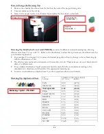
Wrong size metering tip 

Change metering tip 


Chemical proportioner faulty 

Replace chemical proportioner (PDE61-22-3) 


Check valve in filter faulty 

Replace filter (PDE100-11P) 


*  To reduce the risk of fire electrical shock or injury repairs to wiring should only be performed by 


experienced service technicians. 


If you are not experienced in checking electrical wiring contact your nearest authorized service 


center to perform tests and repairs to wiring and switches. 

Summary of Contents for MX3-500RP

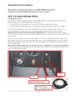
Page 1: ...1 LMANN14 Revised 06 04 2014 Nautilus MX3 500RP Operating Manual...

Page 2: ...9 Water Supply Chemicals 10 Solution Hose Pump Priming 13 Vacuum Hose 14 Foam Downer 15 Pump Out System 16 Pressure Adjustments 17 Shutdown Procedures 18 Accessory Storage 19 Troubleshooting 20 Soluti...

Page 3: ...roperly operate and maintain the machine and to ensure that the equipment operates at its maximum performance level All users must read and understand this manual completely before operating the machi...

Page 4: ...ptional Pump Out Pump Standard Equipment Vacuum Connection 2 Barb or 2 Male Flash Cuff with 2 Male NPT Vacuum Hose 25 X 1 1 2 with 1 1 2 cuff 2 cuff 2 Female Flash Cuff x 1 1 2 hose adapter Carpet Wan...

Page 5: ...e Sold per foot No cuffs AH36 2 cuff for 1 1 2 Vac Hose AH46 1 1 2 cuff for 1 1 2 Vac Hose AH42 1 1 2 Hose Connector PVC AH74 HP Solution Hose 1 4 X 25 w M F Quick Connects AH79D 1 4 Male Quick Connec...

Page 6: ...having the same configuration as the plug No plug adapter should be used with this machine The power cords supplied with this machine are properly sized to handle the electrical load of this machine...

Page 7: ...ns that are at temperatures above 130 F Rinse the solution tank chemical system and pump with fresh water after each day s use Do not allow pump to run dry Always maintain adequate solution level to s...

Page 8: ...rallel 1 Connect the discharge exhaust hose from vacuum 1 to the exhaust pipe on machine base 2 Place the rubber stopper into the vacuum inlet port of vacuum manifold number two 3 Open vacuum gate val...

Page 9: ...e required 20amp circuits are usually found in kitchens and bathrooms An overloaded circuit will not trip the circuit breaker immediately but may not provide sufficient voltage for proper operation an...

Page 10: ...d by the metering tip and the dilution rate can only be changed by changing the metering tip See How to Change the Metering Tip on Page 11 for instructions Chemical Feed Setup Remove the chemical feed...

Page 11: ...dilution rates are based on chemicals with water like viscosity Thicker more viscous chemicals will dilute at a different rate For powdered chemicals a liquid concentrate must be made Mix the concent...

Page 12: ...to the float valve Unhook the float from the beaded chain on the valve Unsnap the hook from the beaded chain on the float Move the bottle down to decrease the water level Move the bottle up to increas...

Page 13: ...he vacuum will pull solution through the pump and prime valve into the vacuum tank Let off the prime valve and your pump is primed As long as there is solution in the tank the pump should remain prime...

Page 14: ...o the 25 Vacuum Hose the 25 vacuum hose is then connected to the vacuum connection port on the MX3 500RP The other end with the 1 1 2 cuff is connected to the cleaning tool When ready to begin cleanin...

Page 15: ...omically NO LABOR is involved to spray or spread defoamer it s all automatic Keeps silicone defoamers off the floor where they can cause resoiling problems The Foam Downer is an attachment that allows...

Page 16: ...loat switch The pump will turn ON OFF during normal operation Pump will be damaged if allowed to run dry When ready to begin cleaning turn the Waste Pump switch to the ON position If not using the was...

Page 17: ...Check the pressure on the gauge o Re adjust as needed to set the machine at the desired pressure o Choose the pressure setting that best meets your type of cleaning Pressure gauge Regulator Unloader...

Page 18: ...vacuum hose and solution hose from the machine If water remains in the solution tank use the vacuum hose and vacuum the excess water from the tank If the optional auto fill system was utilized place...

Page 19: ...500RP has two sets of cord wraps to hold two 12 3 x 25 power cords Carpet Wand Storage The front of the MX3 500RP is designed to hold a S Bend Carpet wand and has two straps to hold it securely Optio...

Page 20: ...m solution tank restricted Repair or replace hose Pump intake hose or fittings leaking Repair or replace hose Tighten clamps or replace fittings Pressure regulator sticking Lube o rings on regulator s...

Page 21: ...ank lid gasket damaged Replace gasket NM5718 Drain valve open Close valve Drain valve leaking Repair or replace drain valve PEA11 Vacuum motor hoses loose leaking Reconnect or replace vacuum motor hos...

Page 22: ...connects AH101B AH102B Solution tank Float too heavy Filled with water Replace float overflowing Float chain tangled Make sure float chain free hanging properly Float too high Adjust chain to set floa...

Page 23: ...flow in high pressure hose Denotes Chemical flow Denotes by pass water flow from pressure regulator Denotes incoming water flow MX3 500RP Solution Flow Path Optional Auto Fill Float Valve Assembly Op...

Page 24: ...agram MX3 500RP Wiring Diagram Cord 1 VAC 1 PUMP OUT SOL PUMP Machine Base COOLING FAN Dual Circuit Indicator VAC1 VAC2 VAC 2 CORD 1 12 3 B L U E B L U E G R E E N O R A N G E SOLUTION PUMP CIRCUIT BR...

Page 25: ...25 VAC 1 PUMP OUT SOL PUMP Machine Base Dual Circuit Indicator VAC 2 PUMP OUT PUMP CORD 2 VAC 2 12 3 CIRCUIT BREAKER 10AMP MX3 500RP Wiring Diagram Cord 2 FLOAT SWITCH...

Page 26: ...witch Power from Cord 2 Do not turn Waste Pump Switch ON unless a hose is connected to the Pump out Outlet port If the Float switch is down the pump will not turn on when the switch is turned on When...

Page 27: ...nal injury or death OPERATION INTERVAL Page CLEAN CHEMICAL FEED FILTER FOOT VALVE Daily After Each Job 28 CLEAN VACUUM SHUTOFF ASSEMBLY SCREEN Daily After Each Job 28 CLEAN HYDRO FILTER II Daily After...

Page 28: ...cuum motors Operating the MX3 500RP without the Vacuum Shutoff Assembly or with a poorly maintained assembly will greatly decrease the life of the vacuum motors and will void the warranty If debris bu...

Page 29: ...ith clean water Examine the o ring lid seal and replace as needed Re install the new or cleaned screen Screw the lid back onto the body and turn clockwise to tighten RINSE OUT RECOVERY TANK Build up o...

Page 30: ...solution hose to the solution outlet female quick connect The other end of the hose should have an open quick connect or no quick connect to allow full flow out of the hose Direct the open end of the...

Page 31: ...ry tank Close the drain valve and dispose of the water CLEAN PUMP INLET FILTER A restricted Pump Inlet Filter can prevent the solution pump from providing adequate pressure for cleaning A restriction...

Page 32: ...s been drawn through the proportioner and mixed with the incoming water The metering tip can be removed from the proportioner to speed up the process Once the rinse solution has been drawn through the...

Page 33: ...ead piston screw so they can be removed from the stem retainer 6 Use a synthetic grease with Teflon such as Ultra Slick or Super Lube to lubricate the o rings on the piston and spindle assembly 7 Re i...

Page 34: ...atches Deep scratches will allow water to flow past gaskets and leak from valve Replace valve if needed Examine the gaskets and replace if cut torn or deformed Raised rounded side of gasket goes towar...

Page 35: ...emical proportioning mechanism 4 Turn the solution pump switch to the ON position and perform the pump priming procedure Hold the priming valve open for a few extra seconds to be sure the anti freeze...

Page 36: ...36 Parts Replacementpartsavailableforrepairof yourMX3 500RP Section 3 KIT A PT054 KIT B PT055 KIT C PT056 MX3 500RP PUMP AP52 PARTS ASSEMBLY...

Page 37: ...BOX 2 6 CRANKCASE 1 7 PLUNGER GUIDE 2 8 HEAD BOLT 6 9 MOUNT BOLT 4 10 WASHER FLAT M6 STAINLESS STEEL 10 NS PUMP COMPLETE WITH MOTOR 1 AP52 NS PUMP COMPLETE WITHOUT MOTOR 1 PT065 NS MOTOR 1 PT066 PUMPT...

Page 38: ...38 OPTIONAL AUTO FILL FLOAT VALVE ASSEMBLY NM5740...

Page 39: ...BRASS KNOB 10 PISTON RETAINER O RING 18 BRASS BODY 3 LOCKING NUT 11 PISTON O RING SMALL 19 POPPET O RING 4 SPRING 12 PISTON WASHER SMALL 20 POPPET 5 SPRING PLATE 13 SPINDLE O RING 21 POPPET SPRING 6 P...

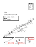
Page 40: ...40 Pump Out Pump PARTS ASSEMBLY...

Page 41: ...41 1 2 3 5 4 4 6 7 8 9 10 11 12 3 8 9 8 9 8 9 39 2...

Page 42: ...42 8 9 15 16 17 18 19 19A 8 9 20 21 22 23 23A 24 25 32 32 37 38 39 40 40 40 41 55 56 9 CONTROL PANEL REAR VIEW BASE BASE SKIRT HINGE SCREWS 55 56...

Page 43: ...43 27 27A 28 29 29 31 31 9 9 32 32 33 34 35 38 37 1 39 13 14 14A 30 30 26 REAR VIEW BASE BASE SKIRT RECOVERY TANK VACUUM PLUG ASSEMBLY 109 106 107 108 36 79...

Page 44: ...44 32 32 43 44 45 37 46 46 47 47 48 50 9 50 9 52 51 53 55 55 TOP VIEW OF BASE 3 58 59 52 90 71 39 70 106 3 58 59 110 110 81...

Page 45: ...45 48 49 49 47 47 47A 47 47A 47 47A 47A 51 51 37 9 54 64 9 54 64 9 54 64 52 VACUUM MOUNTS CONNECTIONS...

Page 46: ...46 44 65 22 66 67 68 69 70 PUMP PRIMING VALVE BOTTOM VIEW OF BASE 60 60 3 59 37 39 57 56 61 62 9 54 9 54 63 55 3 59 61 62 117 71...

Page 47: ...47 9 41 2 BOTTOM VIEW SOLUTION TANK BASE SKIRT 72 1 73 9 9 8 8 39 74 75 76 77 77 78 34 36 36A 30 30 2 115 116 31 80 55...

Page 48: ...48 2 39 1 72 73 73 67 9 30 31 82 83 2 83 82 84 INSIDE SOLUTION TANK BOTTOM VIEW SOLUTION TANK...

Page 49: ...6 87 91 92 94 96 99 9 41A 97 98 100 101 86 102 1 103 PUMP OUT CORD OUTLET FITTINGS LOCATED BEHIND CONTROL PANEL VACUUM SHUTOFF ASSEMBLY INSIDE RECOVERY TANK WITH OPTIONAL PUMP OUT 85 87 95 112 111 93...

Page 50: ...50 92 91 95 94 112 13 14 14A 104 105 1 39 PUMP OUT CONNECTIONS...

Page 51: ...TY 2 10 NM5840 WAND HOLDER STRAP LONG TOP STRAP 30 NM5014 WASHER LOCK SS 11 NM5844 WAND HOLDER BUCKLE 31 NM4063 SCREW 20 X SOCHD SS 12 NM5842 WAND HOLDER STRAP SHORT BOTTOM STRAP 32 NM5722 WHEEL 12 wi...

Page 52: ...0 SPACE 52 PA051 HOSE CLAMP 2 2 75 77 NM5142 SCREW 6 X PPH SS QTY 6 53 NM5705 DECAL VAC CONNECTION 78 NM5756 FAN GUARD WIRE FORMED 54 NM5133 SCREW 20 X 2 00 SOCHD SS 79 NM4031 NUT 6 32 NYLOCK SS 55 NM...

Page 53: ...CAP ASSEMBLY NS NM5705B DECAL DUAL CIRCUIT LIGHT 102 NM5741F FLOAT VACUUM SHUTOFF NS NM5711 DECAL NAUTILUS SIDE QTY 2 103 NM5051 STRAIN RELIEF WATER TIGHT NS NM5758 KIT DUAL CIRCUIT WIRING 104 BR278 E...

Page 54: ...SOLD PER INCH 32 BOTH ENDS HOSE CLAMP SOLUTION HOSE PRIME VALVE TO REC TANK 3 8 ID CLEAR COIL NM5082 SOLD PER INCH 27 BOTH ENDS HOSE CLAMP HP HOSE 1 PUMP TO UNLOADER HP PULSE SOLD ASSEMBLED 50 ITEM 30...

Page 55: ...ll not apply to defects resulting from improper operation lack of maintenance unauthorized modification chemical incompatibility misuse abuse or exposure to freezing temperature conditions It does not...

Reviews: