background image

TM

NS-600

16

step

11

Attach Accessories

Lubrication and Final Check

Cable Tensioning

A.  

A.  

B.  

C.  

A.  

B.  

C.  

D.  

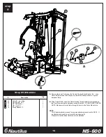
Attach the Handles, Curl Bar, Lat Bar, Chain, Ankle Cuff and Ab Strap to the cable ends 

      using the Cable Clips or store on accessory hooks.

Lubricate Guide Rods using a silicon based lubricant.

Carefully inspect all cables and insure that they are properly seated on the 

      pulleys and that they pass between the cable stops and pulleys.

Double check all hardware and make sure everything is tightened properly.

Tighten the Cable System using the combination of four adjustment locations.  

      These locations are the Double Floating Pulley Brackets and the 
      Selector Rod Top Plate Assembly.  The Cable System should be tightened 
      as tight as possible yet still allow the Selector Pin to freely engage 
      all weights.

After the cables are tensioned load the gym with as high a weight as you feel 

      comfortable with and pull each cable several times to set and stretch the cables.

After the cables are set and stretched, the Cable System may need to be re-

      tensioned.  Tension the cables as described in Step A.

The cables may need to be tensioned periodically as they may stretch slightly 

      over time.

The assembly of your NS-600 is complete.

Should you have any questions or comments regarding your Nautilus gym,
please feel free to contact our Customer Service Department.

The Nautilus Group

1886 Prairie Way

Louisville, CO  80027

1-800-864-1270

www.nautilus.com

Summary of Contents for NS-600

Page 1: ...TM NS 600 Assembly Instructions Rev B...

Page 2: ...1 14679 49 Weight Plate 19 14342 50 Weight Stack Bottom Plate 1 14106 51 Weight Stack Cushion 2 14176 52 Guide Rod 2 14102 CABLE 53 Cable 1 Pulldown Cable 226 1 14791 54 Cable 2 Mid Pulley Cable 96 7...

Page 3: ...4 13 12 11 10 9 8 7 6 5 4 3 2 1 44b TM NS 600 3 A B Compare the Bill of Materials to the box contents to insure that all parts are present before installation begins Unpackage parts and place them nea...

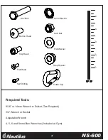
Page 4: ...n Head Cap Head Shim Washer Lock Nut Flat Washer Step Spacer Cable Clip Required Tools 9 16 or 14mm Wrench or Socket Two Required 3 4 Wrench or Socket Adjustable Wrench 4 5 6 and 8mm Allen Wrenches In...

Page 5: ...with the weight stack on the left side To assemble the gym with the weight stack on the right side simply assemble the Rear Frame 2 Top Stack Support Frame 8 and Calf Raise Low Pulley Frame 7 on the...

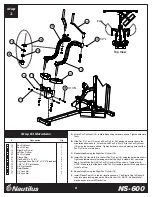
Page 6: ...ware B Attach Leg Extension Assembly 5 to Main Base 1 using hardware shown Do not tighten hardware C Attach Front Upright 4 to Leg Extension Assembly 5 using hardware shown Do not tighten hardware D A...

Page 7: ...Fly Pulley Bracket 21 to Leg Extension Assembly using hardware shown Tighten hardware firmly E Install Low Row Cable 55 through Calf Raise Low Pulley Frame 7 See Detail A Feed the looped end of the c...

Page 8: ...c Fly Arm can rotate freely C Repeat step B using the Right Pec Fly Arm 18 D Install Pec Fly Handle 20 in the Left Pec Fly Arm 19 using the hardware shown Tighten hardware securely making sure that th...

Page 9: ...Align Shaft and tighten two set screws 82 as shown C Attach Press Arm Handles 14 15 using the hardware shown Tighten hardware firmly D Slide the Roller Bar 41 through the Leg Extension tube Either of...

Page 10: ...n Leg Extension Assembly in the slot shown Use the Pop Pin 34 to adjust height NOTE Pop Pin is threaded so that the seat can be locked in place E Attach Back Pad Tube 24 to Back Pad 28 using hardware...

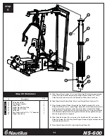
Page 11: ...d the Top Weight Assembly 48 on the Guide Rods 52 as shown Install Weight Plates 49 so that the selector pin hole faces forward and is located on the bottom of the plate Install the Top Weight Assembl...

Page 12: ...e hardware shown in detail B Tighten hardware securely TM NS 600 12 Step 7 Materials step 7 Description Qty 2 5 1 2 3 6 5 4 31 44 52 63 65 74 77 79 F Route Cable 1 around the 4 1 2 Pulley installed in...

Page 13: ...e lower Pulley on the Double Floating Pulley Bracket 30 as shown E Route Cable 2 54 around the 4 1 2 Pulley on the Pec Fly Double Floating Pulley Bracket 30 Continue by routing Cable over the 3 1 2 Pu...

Page 14: ...5 under the Cable Housing 9 and attach the termination to the Rear Frame using the hardware shown in detail A DO NOT OVERTIGHTEN NOTE Make sure to route Cable through the hole in the Pulley Mount tube...

Page 15: ...able around the Pulley on the left side of the Leg Extension Assembly as shown Be sure that the Low Pulley Cover 33 does not interfere with the Cable D Route Cable 4 56 around the 6 Pulley in the Pec...

Page 16: ...ting Pulley Brackets and the Selector Rod Top Plate Assembly The Cable System should be tightened as tight as possible yet still allow the Selector Pin to freely engage all weights After the cables ar...

Page 17: ...Screw 3 L w locktite 2 14260 38b Cap Head Screw 7 16 x 1 1 2 L 1 14261 39b Button Head Allen Screw 1 4 x 3 4 9 14278 40b Self Drilling Screw 8 x 5 8 L 6 14773 41b Bearing 2 14271 42b Hand Grip 6 L 4 1...

Page 18: ...87 20a Allen Screw 3 8 x 1 L w Thread Lock 2 14505 21a 6205 Bearing 4 14508 22a Pan Head Allen 3 8 x 3 L w Thread Lock 1 14538 23a 1 2 Hex Nut 3 14527 24a Hex Bolt 3 8 x 1 1 2 L 1 14522 25a Hex Bolt 3...

Page 19: ...s 1 14478 13a Plastic Cap 2 14187 14a Double Pulley w Bearings and Bushings 1 14484 22b Bushing 19 45 x 12 8 x 18h 2 14200 16a Step Spacer 25 x 17 x 25 7h 2 14491 17a Leg Hold Down Locking Pin 1 14495...

Reviews: