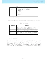
Table 4.10 continued from previous page
Field ID
Description
Stall
IAS speed value starting which a alarm is triggered (TAS Probe
needed).
4.9.12 Calibration
All models of the new Flymaster SD series include a magnetometer and accelerometer sensor. Using these
sensors the NAV SD can provide G-Force and magnetic compass heading. Even though the compass is
digital there is a tilt compensation algorithm that ensures accurate compass heading even when the NAV
SD is inclined.
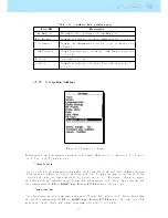
The Calibration menu option allows the user to calibrate the NAV SD accelerometer and magnetometer
sensors. Calibration is particularly important for the magnetometer since without it you will get inaccurate
data from the compass. Despite all Flymaster instruments being factory calibrated errors can be introduced
due to several external inuences, such as the presence of strong magnetic elds or the time. In order to
eliminate these errors a proper magnetometer calibration should be made. Calibration parameters are kept
when the NAV SD is turned o, reset or when a rmware update is done. The magnetometer calibration
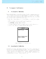
process is described in Section
8.2
.
The NAV SD magnetic compass is very sensible to external magnetic elds. In order to get
good readings ensure that there are no interference sources nearby.
The accelerometer calibration is not so critical as the magnetometer. The accelerometer is less sensitive to
external factors and the errors are usual negligible for the propose. However, if you notice strange readings
(eg. G-Force value dierent from 1 when the instrument is at rest) a calibration should be made. The
accelerometer calibration process is described in Section
8.1
.
4.9.13 Polar
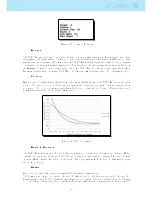
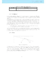
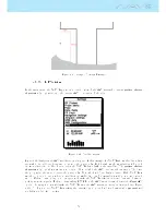
Figure 4.35: Polar Parabola
The Polar menu option allows the user to dene the glider polar curve. The polar curve is approximated
by a parabola which is dened by 3 points identied by Max; Between; Min (see Figure
4.35
). Each point
corresponds to a pair <horizontal speed in km/h, vertical speed m/s> where both values are positive,
that are dened by the user (see Figure
4.36
). In order to avoid errors the Max and Min points should
correspond respectively to the maximum and minimum horizontal speed of the glider. The point Between
should be some point between the Maximum and Minimum.
48
Summary of Contents for Flymaster NAV SD
Page 1: ...User manual Version 3 0...
Page 54: ...Figure 4 42 GPS Reset 53...

